Underground pipe gallery wiring device for communication pipeline engineering

A technology for underground pipe gallery and communication pipeline, which is applied in the directions of cable installation, cable installation, cable installation device, etc. in underground pipelines, can solve the problem that the rapid wiring and removal of temporary communication cables cannot be realized, the operation is inconvenient, and the operation efficiency is low. and other problems, to achieve the effect of improving work efficiency, rapid dismantling, and realizing dismantling.

Pending Publication Date: 2021-11-30
荆门市诚顺知识产权服务有限公司
View PDF0 Cites 0 Cited by
  • Summary
  • Abstract
  • Description
  • Claims
  • Application Information

AI Technical Summary

Problems solved by technology

The underground pipe gallery is one of the important places for the wiring of communication cables such as optical cables in the communication pipeline project. In the communication pipeline project, due to temporary operation factors such as equipment maintenance, emergency rescue and disaster relief, it is sometimes necessary to temporarily lay communication cables in the underground pipe gallery , when the temporary work is over, the laid communication cables need to be removed. The traditional temporary cable laying method is to fix the cable brackets on the inner wall of the underground pipe gallery through expansion bolts, and then erect the wire pipes on the cable brackets. Then use the wire threader to thread the optical cable and other communication cables into the line pipe. However, this method is inefficient and inconvenient to operate, and cannot realize the rapid wiring and removal of temporary communication cables.

Method used


Image

  • Underground pipe gallery wiring device for communication pipeline engineering
  • Underground pipe gallery wiring device for communication pipeline engineering
  • Underground pipe gallery wiring device for communication pipeline engineering

Examples


Embodiment Construction

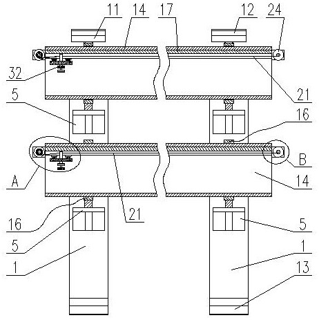
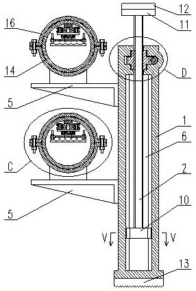
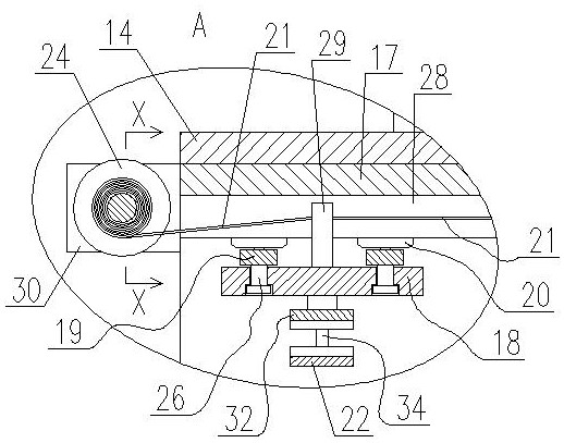
[0020] Depend on figure 1 and figure 2 As shown, the underground pipe corridor wiring device used for communication pipeline engineering includes a supporting mechanism and a pipeline mechanism, and the supporting mechanism includes a support 1, a screw 2, a screw sleeve 3, a worm 4 and a bracket 5, Depend on Figure 6 and Figure 10 As shown, a connected vertical groove 6 and a cavity 7 are provided in the support 1, the screw sleeve 3 is movably installed in the cavity 7, and a worm wheel 8 is arranged on the circumference of the screw sleeve 3, so that The worm 4 is movably installed in the cavity 7, the worm 4 meshes with the worm wheel 8, and one end of the worm 4 passes through the support 1, and a handle 9 is arranged at the end of the worm 4, and the screw 2 rotates Placed in the screw sleeve 3, and penetrated in the vertical groove 6, by Figure 8 As shown, a limit block 10 is arranged on the screw rod 2 in the vertical groove 6, the upper end of the screw rod 2 ...


PUM


Abstract

The invention discloses an underground pipe gallery wiring device for communication pipeline engineering, vertical groove and a cavity which are communicated with each other are formed in a support, a screw sleeve is movably mounted in the cavity, a worm gear is arranged on the periphery of the screw sleeve, a worm is movably mounted in the cavity, the worm is meshed with the worm gear, one end of the worm penetrates out of the support, the end of the worm is provided with a rocker, the threaded rod is arranged in the threaded sleeve in a rotating mode and arranged in the vertical groove in a penetrating mode, a limiting block is arranged on the portion, located in the vertical groove, of the threaded rod, the upper end of the threaded rod penetrates out of the support, a top plate is arranged at the upper end of the threaded rod, a first rubber pad is arranged on the upper portion of the top plate, and a second rubber pad is arranged at the bottom of the support. The device has the advantages that rapid wiring of the underground pipe gallery of the communication pipeline engineering is achieved, operation is quite convenient and rapid, the working efficiency is effectively improved, the wall structure of the underground pipe gallery is not damaged, and rapid dismounting can be achieved.

Description

technical field [0001] The present invention relates to the technical field of communication pipeline engineering, and more specifically relates to the technical field of communication pipeline engineering wiring devices. Background technique [0002] With the rapid development of economy and technology level, communication pipeline is an important equipment carrier in the process of my country's information industry construction, and the quality of communication pipeline engineering will be directly related to the process of my country's informatization. The underground pipe gallery is one of the important places for the wiring of communication cables such as optical cables in the communication pipeline project. In the communication pipeline project, due to temporary operation factors such as equipment maintenance, emergency rescue and disaster relief, it is sometimes necessary to temporarily lay communication cables in the underground pipe gallery , when the temporary work...

Claims


Application Information

Patent Timeline
IPC IPC(8): G02B6/50G02B6/44H02G9/06H02G1/08
CPCG02B6/50H02G9/06H02G1/088G02B6/545
Inventor 罗晓声
Owner 荆门市诚顺知识产权服务有限公司
Why Eureka
Try Eureka