Time domain multiplexing frequency shift chirp keying modulation and quadrature modulation extension method thereof

A technology of key modulation and time domain multiplexing, which is applied in the field of communication and can solve problems such as limited system data rate and spectral efficiency improvement

Active Publication Date: 2021-11-30
BEIJING INSTITUTE OF TECHNOLOGYGY
View PDF2 Cites 6 Cited by
  • Summary
  • Abstract
  • Description
  • Claims
  • Application Information

AI Technical Summary

Problems solved by technology

Although this method does not cause a serious degradation in bit error rate performance, it can only transmit one m

Method used


Image

  • Time domain multiplexing frequency shift chirp keying modulation and quadrature modulation extension method thereof
  • Time domain multiplexing frequency shift chirp keying modulation and quadrature modulation extension method thereof
  • Time domain multiplexing frequency shift chirp keying modulation and quadrature modulation extension method thereof

Examples


Embodiment 1

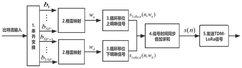
[0047] The following is a detailed decomposition of the time domain multiplexing frequency shift chirp keying modulation method:

[0048] Step 1: group 1400 bits of a frame into each group of 2SF=14 bits, and perform serial-to-parallel conversion on each group of 2SF=14 bits.

[0049] Step 2: Set the nth bit of each group as d[n], convert the first SF=7 binary bits into Gray code, and convert Gray code into decimal number:

[0050]

[0051] Convert the remaining 7 binary bits into Gray code and convert to decimal number:

[0052]

[0053] Step 3: the corresponding information w of the first SF=7 bits u Carried by the cyclically shifted up-chirp signal, SF represents the spreading factor, B represents the symbol bandwidth, and the symbol sampling interval is expressed as T s =1 / B, carry information w u The discrete up-chirp signal of is expressed as:

[0054]

[0055] where n=0,1...2 SF -1, similarly, the corresponding information of the remaining 7 bits is w d ,...

Embodiment 2

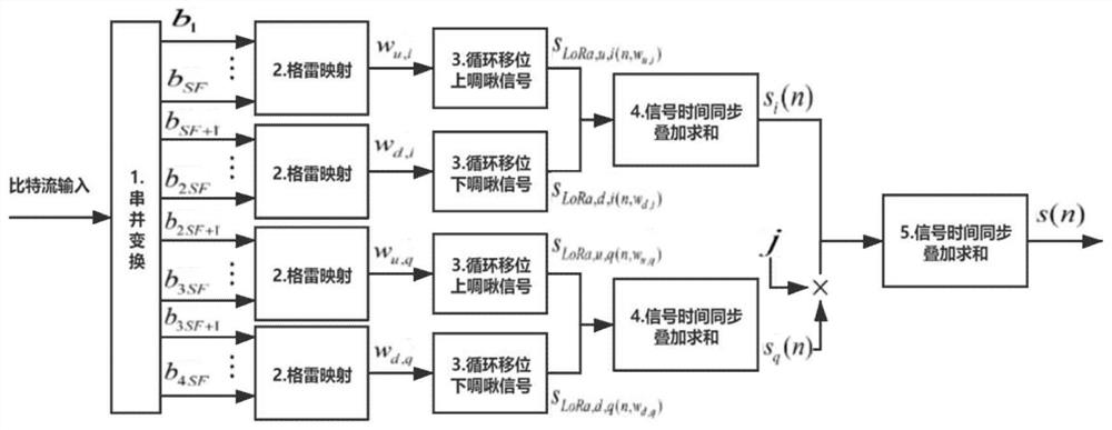
[0077]The following is a detailed decomposition of the orthogonal time domain multiplexing frequency shift chirp keying modulation method:

[0078] Step 1: grouping 1400 bits of a frame into each group of 4SF=28 bits, and performing serial-to-parallel conversion of each group of 2SF=14 bits.

[0079] Step 2: Set the nth bit of each group as d[n], convert the first SF=7 binary bits into Gray code, and convert Gray code into decimal number:

[0080]

[0081] Convert the second group of 7 binary bits into Gray code and convert to the corresponding decimal number:

[0082]

[0083] Convert the second group of 7 binary bits into Gray code and convert to the corresponding decimal number:

[0084]

[0085] Convert the second group of 7 binary bits into Gray code and convert to the corresponding decimal number:

[0086]

[0087] Step 3: the corresponding information w of the first SF=7 bits u,i Carried by the cyclically shifted up-chirp signal, SF represents the spreadi...


PUM


Abstract

The invention provides a time domain multiplexing frequency shift chirp keying modulation and quadrature modulation extension method thereof, which can improve the data transmission rate and the spectrum efficiency, ensure that the bit error rate performance is basically unchanged, and greatly improve the throughput rate. The method includes the following steps: grouping information bits input into a modulator by a sending end of a time domain multiplexing frequency shift chirp keying modulation system, performing serial-parallel conversion and Gray mapping on SF bits in one group, then selecting an upper chirp signal of periodic frequency shift, performing serial-parallel conversion and Gray mapping on SF bits in the other group, and adding and then transmitting the upper chirp signal and the lower chirp signal carrying the information; receiving, by a receiving end of the time domain multiplexing frequency shift chirp keying modulation system, the signals, and multiplying the received signals respectively by original lower chirp signals and upper chirp signals, performing discrete Fourier transform on the respectively multiplied received signals, and acquiring the position information of the highest peak from two frequency spectrums, and demodulating corresponding sending information bits.

Description

technical field [0001] The invention belongs to the technical field of communication, and relates to a time-domain multiplexing frequency shift chirp keying modulation and an orthogonal modulation extension method thereof, which are suitable for long-distance (Long Range, LoRa) communication, chirp spread spectrum modulation (Chirp spread spectrum , CSS) technology and frequency shift chirp modulation (Frequency Shift Chirp Modulation, FSCM) technology waveform design, transmission scheme and quadrature modulation expansion scheme. Background technique [0002] As a low-power wide-area IoT technology, LoRa has been successfully applied in a large number of IoT scenarios. It has the advantages of scalable bandwidth, strong anti-interference ability, and high receiving sensitivity. LoRa adopts Chirp Spread Spectrum Modulation (CSS) signal to modulate data, so that the receiver has high sensitivity and can accurately recover information under the condition of low signal-to-nois...

Claims


Application Information

Patent Timeline
IPC IPC(8): H04L27/34H04L27/36H04L27/38
CPCH04L27/34H04L27/36H04L27/38Y02D30/70
Inventor 王华安世祥何东轩于泉涛
Owner BEIJING INSTITUTE OF TECHNOLOGYGY
Why Eureka
Try Eureka