A bioreactor post-operation cleaning device

A bioreactor and cleaning device technology, applied in the direction of cleaning hollow objects, cleaning methods and utensils, chemical instruments and methods, etc., can solve the problems of photobioreactor damage, no protective structure, and difficult cleaning of the fixed position of the clamp block, etc. , to achieve the effect of reducing the possibility of damage, good cleaning effect, flexible and convenient use

Active Publication Date: 2021-12-31
沃钛思(南通)生物科技有限公司
View PDF6 Cites 0 Cited by
  • Summary
  • Abstract
  • Description
  • Claims
  • Application Information

AI Technical Summary

Problems solved by technology

[0003] Existing cleaning devices, such as the public document CN208853403U, in this patent document, the cleaning device can effectively clean the outer wall of the photobioreactor, but the cleaning effect on the inner wall of the photobioreactor is not good, and in the process of rotating and cleaning, When the photobioreactor is shifted, there is no protective structure, which will easily cause the photobioreactor to be thrown out of the tray, which will easily cause damage to the photobioreactor. In this patent, the photobioreactor is fixed by clamping blocks. The position where the clamp block is fixed is more difficult to clean

Method used


Image

  • A bioreactor post-operation cleaning device
  • A bioreactor post-operation cleaning device
  • A bioreactor post-operation cleaning device

Examples


Embodiment 1

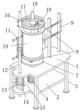
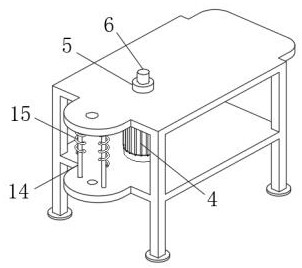
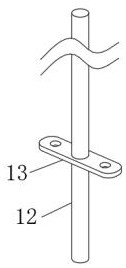
[0032] Such as Figure 1-Figure 5As shown, the upper and lower platen structure of a bioreactor post-operation cleaning device includes an upper workbench 1, a middle workbench 2 is arranged below the upper workbench 1, and a No. 1 rotating rod 6 is arranged on the upper workbench 1. The side positions of the upper workbench 1 and the middle workbench 2 are provided with side movable rods 12, the upper movable pipes 16 are arranged on the side movable rods 12, and the middle fixed rods 18 are arranged at the side positions of the upper movable pipes 16, which are characterized in that: a An upper and lower platen structure 8 is provided above the number rotating rod 6, and the upper and lower platen structures 8 include a lower platen 20 and an upper pressure ring 26, the upper pressure ring 26 is located above the lower platen 20, and the middle fixed rod 18 is provided with There is an inner cleaning structure 10, the inner cleaning structure 10 includes an inner movable rod...

Embodiment 2

[0034] Such as Figure 1-Figure 5 As shown, the parts that are the same as or corresponding to those in the first embodiment adopt the reference numerals corresponding to those in the first embodiment, and only the differences from the first embodiment will be described below. The difference between this embodiment two and embodiment one is: as Figure 5 As shown, a kind of internal cleaning structure of the cleaning device after the operation of the bioreactor, the quantity of the inner movable rod 29 is two, and is movably installed with the fixed rod 18 in the middle, the inner movable rod 29 is provided with an inner spring 31, and the inner movable rod One end of 29 is provided with an inner baffle 50, when the reduction motor 4 starts, because the inner movable rod 29 is fixed by the middle fixed rod 18, thereby keeping the inner movable rod 29 still, the inner spring 31 pushes the inner brush plate 30 outward Move so that the bristles on the inner brush plate 30 contac...

Embodiment 3

[0036] Such as Figure 1-Figure 5 As shown, the parts that are the same as or corresponding to those in the first embodiment adopt the reference numerals corresponding to those in the first embodiment, and only the differences from the first embodiment will be described below. The difference between this embodiment two and embodiment one is: as Figure 6 and Figure 7 As shown, a kind of external cleaning structure of the cleaning device after the operation of the bioreactor, the lower part of the upper moving ring 35 is provided with a lower moving ring 32, the side of the lower moving ring 32 is provided with a No. 2 bolt 33, and the lower moving ring The lower clamping rod 34 is fixedly installed on the body 32, and the position corresponding to the lower clamping rod 34 on the upper moving ring body 35 is provided with an upper clamping groove 36, and the outer movable rod 39 is installed with the side connecting plate 37 through the outer casing 38, and the outer movable...


PUM


Abstract

The invention discloses a cleaning device for a bioreactor after operation, which belongs to the field of cleaning devices and comprises an upper workbench, a middle workbench is arranged below the upper workbench, and a No. 1 rotating rod is arranged on the upper workbench. The side positions of the upper workbench and the middle workbench are provided with side movable rods, the upper movable pipes are arranged on the described side movable rods, and the middle fixed rods are arranged at the side positions of the upper movable pipes. The device for cleaning a bioreactor after operation according to the present invention, through the upper and lower pressure plate structure, it is convenient to completely expose the outer side wall and the inner side wall of the bioreactor, and it is convenient to quickly replace the workpiece. The reactor is protected to reduce the possibility of damage caused by being thrown out. The inner cleaning structure is provided to facilitate cleaning of the inner wall, and the outer cleaning structure is provided to facilitate cleaning of the outer wall. It is flexible in use and does not hinder the replacement of workpieces.

Description

technical field [0001] The invention relates to the field of cleaning devices, in particular to a cleaning device after operation of a bioreactor. Background technique [0002] Photobioreactor refers to a type of device that can be used for photosynthetic microorganisms and their photosynthetic tissue or cell culture. This kind of reactor has a similar structure to general bioreactors and requires certain The light, temperature and nutrients are used to cultivate microorganisms and adjust and control the environment of the system. After the photosynthetic microorganisms are completed, the photobioreactor needs to be cleaned to facilitate the next operation, so it needs to be used Clean unit. [0003] Existing cleaning devices, such as the public document CN208853403U, in this patent document, the cleaning device can effectively clean the outer wall of the photobioreactor, but the cleaning effect on the inner wall of the photobioreactor is not good, and in the process of rot...

Claims


Application Information

Patent Timeline
Patent Type & Authority Patents(China)
IPC IPC(8): B08B9/36B08B13/00
CPCB08B9/36B08B13/00
Inventor 滕小锘邱忠孔迪
Owner 沃钛思(南通)生物科技有限公司
Why Eureka
Try Eureka