Clamping device capable of facilitating drill bit replacement and used for drilling machine

A technology of clamping device and drill bit, which is applied in the field of mechanical processing, can solve the problems of reducing production efficiency, easy shaking of the drill bit, and reducing the work efficiency of staff, and achieves the effects of convenient operation, small size and simple structure

Inactive Publication Date: 2021-12-03
陈露
View PDF0 Cites 0 Cited by
  • Summary
  • Abstract
  • Description
  • Claims
  • Application Information

AI Technical Summary

Problems solved by technology

Usually, the rotation of the drill bit is the main movement, and the axial movement of the drill bit is the feed movement. The drilling machines currently on the market are not easy to replace the drill bit when the staff is using it. After the replacement, the drill bit is eas

Method used


Image

  • Clamping device capable of facilitating drill bit replacement and used for drilling machine
  • Clamping device capable of facilitating drill bit replacement and used for drilling machine
  • Clamping device capable of facilitating drill bit replacement and used for drilling machine

Examples


Embodiment 1

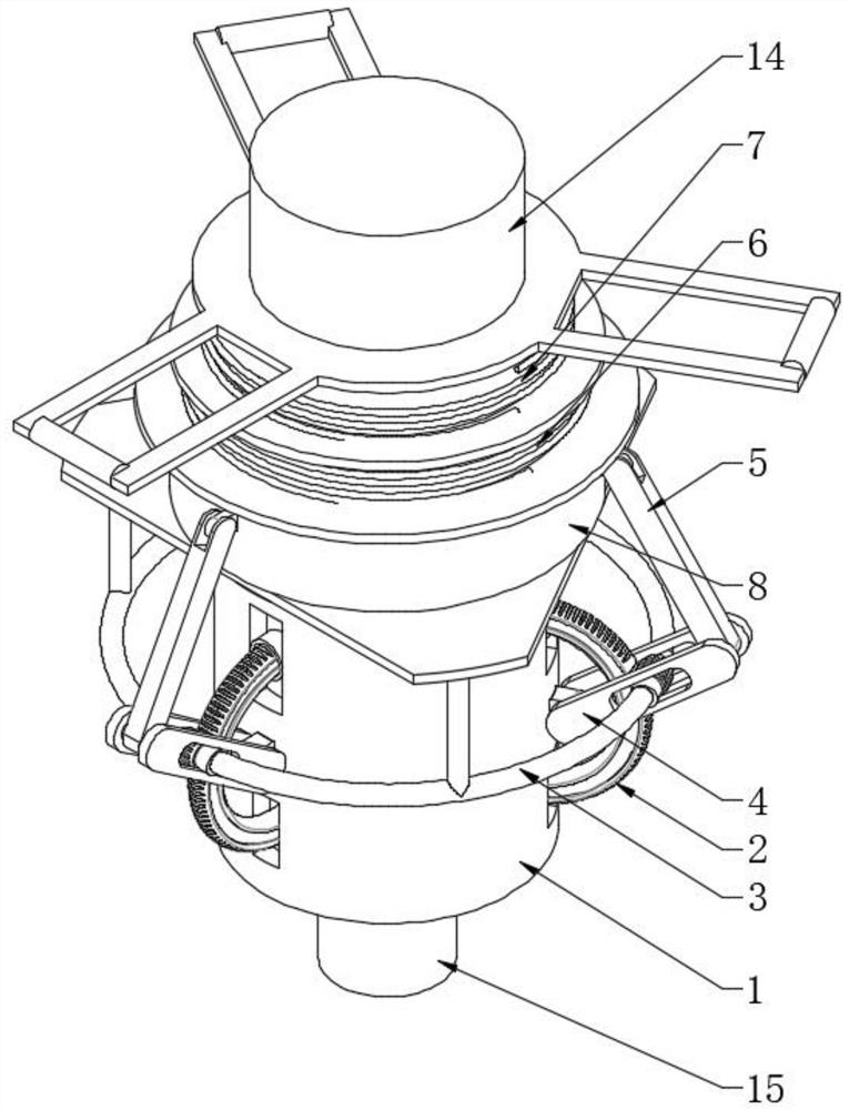
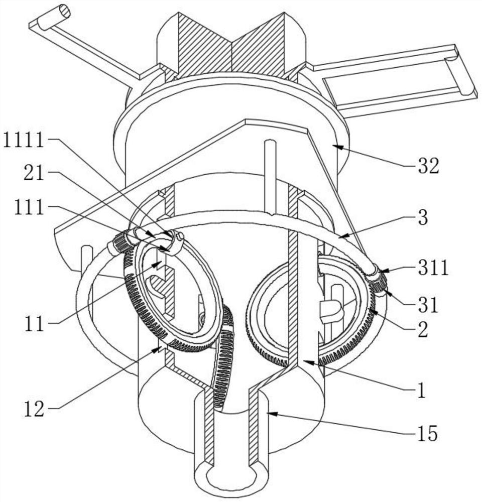
[0027] see Figure 1-4 , a kind of clamping device that is used for drilling machine to be easy to replace drill bit, comprises fixed sleeve 1, clamping ring 2, limit ring 3, pressing arm 4, spring one 6, spring two 7 and auxiliary sleeve 8, the peripheral wall of fixed sleeve 1 A positioning hole 11 and a limiting hole 12 are provided. The limiting hole 12 is located on one side of the positioning hole 11 along the axial direction of the fixed sleeve 1. The number of the positioning holes 11 is at least three and is evenly distributed in the circumferential direction. A positioning sleeve 111 is rotatably connected in the hole 11, and the forming shaft of the clamping ring 2 passes through the positioning sleeve 111 and the limiting hole 12 in sequence. The outer wall is provided with an annular groove 21 coaxially distributed, and the positioning sleeve 111 is fixedly provided with a limit shaft 1111 slidingly fitted with the annular groove 21, that is to say, the clamping r...

Embodiment 2

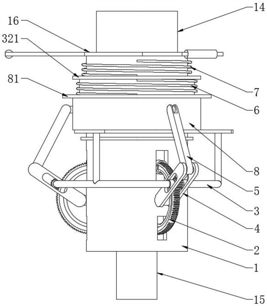
[0029] see Figure 4 The difference with Embodiment 1 is that the outer peripheral wall of the annular limiting plate 16 is fixedly provided with a grooved baffle 161. It should be pointed out that this grooved baffle 161 acts as a fulcrum, and the horizontal axis in the middle of the grooved baffle 161 can be Sleeve the sleeve, when it is necessary to slide control the guide sleeve 32 and the auxiliary sleeve 8, with the help of the external seesaw, with the sleeve as the fulcrum, the external of the auxiliary sleeve 8 is fixed with an annular limit plate 3 81, the annular limit plate Three 81 and annular limit plate one 321 act as contact baffles of the seesaw, and then manual control is convenient for operation.

[0030] Working principle: When in use, the docking shaft 14 is fixedly connected with the output shaft of the drilling machine. When replacing the drill bit, use the pry plate to pry the ring-shaped limit plate 3 81 with the grooved baffle 161 as the fulcrum, the ...


PUM


Abstract

The invention discloses a clamping device capable of facilitating drill bit replacement and used for a drilling machine. The clamping device comprises a fixing sleeve, clamping rings, a limiting ring, pressing arms, a first spring, a second spring and an auxiliary sleeve. According to the clamping device, the fixing sleeve is arranged, the at least three clamping rings which are evenly distributed in the circumferential direction are arranged on the fixing sleeve, the clamping rings swing and rotate relative to the fixing sleeve, the evenly-distributed clamping rings swing oppositely and can clamp a drill rod stretching into the fixing sleeve, in other words, when the drill rod is inserted into the fixing sleeve from the lower part, the drill rod can conveniently enter the space defined by the evenly-distributed clamping rings, the limiting ring is arranged outside the fixing sleeve, a gear meshing with the clamping rings is arranged on the limiting ring, the gear is fixedly matched relative to the limiting ring, a guide sleeve connected with the limiting ring is arranged on the fixing sleeve in a sleeved mode, the guide sleeve is sleeved with the auxiliary sleeve, the pressing arm matched with the gear is hinged to the outer part of the fixing sleeve, one end of the pressing arm is hinged to the outer wall of the auxiliary sleeve through a connecting rod, the guide sleeve is in elastic sliding fit with the auxiliary sleeve and the fixing sleeve, and the drill rod is elastically controlled and locked.

Description

technical field [0001] The invention relates to the technical field of mechanical processing, in particular to a clamping device for a drilling machine which is convenient for replacing a drill bit. Background technique [0002] Drilling machine refers to a machine tool that mainly uses a drill bit to process holes in a workpiece. Usually, the rotation of the drill bit is the main movement, and the axial movement of the drill bit is the feed movement. The drilling machines currently on the market are not easy to replace the drill bit when the staff is using it. After the replacement, the drill bit is easy to shake, which will reduce the work efficiency of the staff. It is necessary to use a wrench to apply force to operate, which increases the workload of the staff, and the replacement operation of the staff is inconvenient, and the production efficiency will also be reduced. [0003] For this reason, the present invention provides a kind of clamping device that is used for...

Claims


Application Information

Patent Timeline
IPC IPC(8): B23Q3/00
CPCB23Q3/00
Inventor 陈露
Owner 陈露
Why Eureka
Try Eureka