
Built-in scrap iron treatment system of metal-working machine

A metal processing and processing system technology, applied in metal processing machinery parts, metal processing equipment, manufacturing tools, etc., can solve the problems of iron filings returning to the factory for processing, manual cleaning, and increasing economic expenses, so as to facilitate cleaning and transportation, It is convenient to return to the factory for processing and saves economic expenses.

Pending Publication Date: 2021-12-03
诸暨鑫运机械设备有限公司
View PDF0 Cites 0 Cited by
  • Summary
  • Abstract
  • Description
  • Claims
  • Application Information

AI Technical Summary

Problems solved by technology

[0002] As we all know, in the processing of metal machine tools, metal scraps must be cut out. There is a relatively common problem, that is, the scraps of metal cutting often hurt the human body. Such injuries not only cause pain to workers, but even cause But the existing metal processing machine tools only have a single storage board for iron filings, and the iron filings need to be cleaned manually, but the iron filings are small and numerous, and manual cleaning is troublesome, and the oil in the iron filings cannot be filtered, which makes the subsequent It is very troublesome to return to the factory for processing. It cannot realize the sustainable recycling of oil and increase the economic expenditure. It cannot squeeze and heat the iron filings, so as to realize the lumpy sliding of the iron filings, which makes the cleaning and transportation of the iron filings time-consuming and laborious, and increases the economic burden.

Method used


Image

  • Built-in scrap iron treatment system of metal-working machine
  • Built-in scrap iron treatment system of metal-working machine
  • Built-in scrap iron treatment system of metal-working machine

Examples


Embodiment Construction

[0023] The following are specific embodiments of the present invention and in conjunction with the accompanying drawings, the technical solutions of the present invention are further described, but the present invention is not limited to these embodiments.

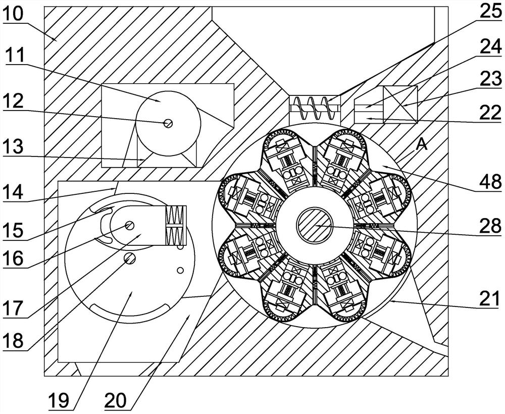
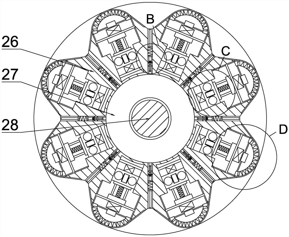
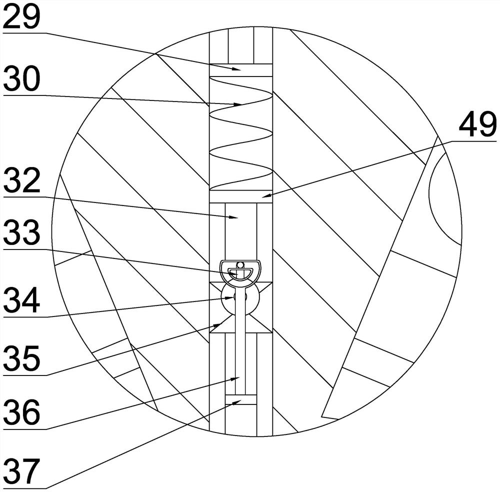
[0024] Such as figure 1 As shown, a metal processing machine tool has a built-in iron filings processing system, which includes a housing 10, and the right side of the housing 10 is provided with an iron filings processing chamber 48, and the iron filings processing chamber 48 is provided with an iron filings processing device, and inside the iron filings processing device There is a filtering device, the filtering device is used to filter the oil in the iron filings, the iron filings processing device is equipped with an extrusion device, the extrusion device is used to squeeze the iron filings after degreasing, and the iron filings processing device is equipped with a heating The heating device is used to heat the iron f...


PUM


Abstract

The invention belongs to the field of metal processing, and relates to a built-in scrap iron treatment system of a metal-working machine. The system comprises a shell, wherein a scrap iron treatment cavity is formed in the right side of the shell; a scrap iron treatment device is arranged in the scrap iron treatment cavity; a filtering device is arranged in the scrap iron treatment device; an extrusion device is arranged in the scrap iron treatment device; a heating device is arranged in the scrap iron treatment device; a feeding cavity is formed in the upper side of the shell; a feeding device is arranged in the feeding cavity; a discharging cavity is formed in the left side of the shell; and a discharging device is arranged in the discharging cavity. According to the scrap iron treatment device in the metal-working machine, oil in scrap iron can be filtered, the oil can be recycled continuously, the scrap iron can be extruded after being deoiled, and the scrap iron is heated while being extruded, so that the scrap iron can be slightly melted on the surface, the scrap iron is bonded, the scrap iron can be fed in order in the feeding process, and discharging can be conducted after the scrap iron is bonded.

Description

technical field [0001] The invention belongs to the field of metal processing, and in particular relates to a built-in iron scrap processing system of a metal processing machine tool. Background technique [0002] As we all know, in the processing of metal machine tools, metal scraps must be cut out. There is a relatively common problem, that is, the scraps of metal cutting often hurt the human body. Such injuries not only cause pain to workers, but even cause But the existing metal processing machine tools only have a single storage board for iron filings, and the iron filings need to be cleaned manually, but the iron filings are small and numerous, and manual cleaning is troublesome, and the oil in the iron filings cannot be filtered, which makes the subsequent It is very troublesome to return to the factory for processing. It cannot realize the sustainable recycling of oil and increase the economic expenditure. It cannot squeeze and heat the iron filings to realize the lu...

Claims


Application Information

Patent Timeline
IPC IPC(8): B23Q11/00
CPCB23Q11/00B23Q11/0042
Inventor 刘桥
Owner 诸暨鑫运机械设备有限公司
Learn More