Check patentability & draft patents in minutes with Patsnap Eureka AI!

Vertical bin storage structure for chemical fertilizer

A fertilizer and storage technology, applied in chemical instruments and methods, containers, mixers, etc., can solve the problems of clogging of the discharge port of fertilizer, caking of fertilizer particles, and difficulty in outputting fertilizer, so as to avoid caking, improve full contact, Avoid the effect of clumping

Pending Publication Date: 2021-12-03
山西东锦肥业有限公司
View PDF0 Cites 0 Cited by
  • Summary
  • Abstract
  • Description
  • Claims
  • Application Information

AI Technical Summary

Problems solved by technology

[0002] During the storage and application of high-humidity fertilizers, since the fertilizers contain a lot of water, if they are only stored in traditional storage bins, it will often cause agglomeration between fertilizer particles, which will seriously lead to agglomeration The fertilizers block the discharge port, making it difficult to output the fertilizers stored in the vertical bin; and the high-humidity fertilizer is attached to the inner wall of the vertical bin, causing damage to the vertical bin

Method used


Image

  • Vertical bin storage structure for chemical fertilizer
  • Vertical bin storage structure for chemical fertilizer
  • Vertical bin storage structure for chemical fertilizer

Examples


Embodiment 1

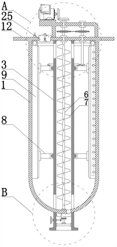
[0024] see Figure 1-3 , a vertical storage structure for chemical fertilizers, comprising a vertical warehouse body 1, a material turning mechanism, a scraping mechanism, and an air blowing mechanism, the vertical warehouse body 1 is vertically arranged, and the material turning mechanism, the scraping mechanism, and the blowing mechanism are all installed in the vertical warehouse The inner side of the body 1, and the turning mechanism and the scraping mechanism are both connected to the driving motor 2, and the driving motor 2 drives the returning mechanism and the scraping mechanism to move in the vertical bin body 1;

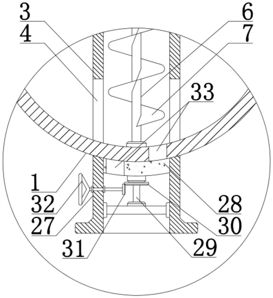
[0025] The material turning mechanism includes: the feeding pipe body 3 vertically consolidated in the vertical bin body 1 along the central position of the vertical bin body 1, the feed port 4 and the discharge port respectively provided at the bottom and top of the clinker pipe body. Port 5, the power shaft 6 that is nested and installed at the inner cent...

Embodiment 2

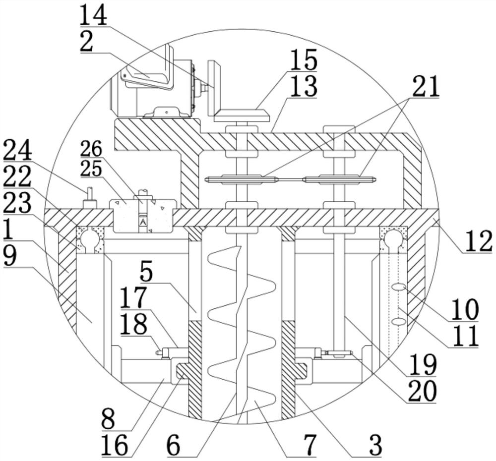
[0029] see Figure 1-2 , and according to Embodiment 1, the mode of power connection between the drive motor 2 and the power shaft 6 and the scraper 9 is described:

[0030] The top of the vertical warehouse body 1 is sealed and consolidated with a mounting plate 12, and a mounting bracket 13 is fixedly installed on the mounting plate 12, and the driving motor 2 is fixedly mounted on the mounting bracket 13, which ensures the stable installation of the driving motor 2 on the vertical warehouse body 1 The first reversing gear 14 is fixedly installed on the rotating shaft of the driving motor 2, the top of the power shaft 6 is passed out by the mounting plate 12, and the second reversing gear 15 is fixedly installed on the part of the power shaft 6 passing out of the mounting plate 12 The first reversing gear 14 is engaged with the second reversing gear 15, and the driving motor 2 drives the first reversing gear 14 to rotate, thereby driving the second reversing gear 15 and the ...

Embodiment 3

[0034] Please refer to 1-2, this article describes the communication mechanism in detail and technical supplements according to the embodiment 1-2. The opposite surfaces of the connecting ring body 22 and the second connecting ring body 23 are in close contact and keep relative rotation. The first connecting ring body 22 is fixedly installed on the lower surface of the mounting plate 12, and the second connecting ring body 23 is fixedly installed on each group of scrapers. The top of the plate 9, the contact surfaces of the first connecting ring body 22 and the second connecting ring body 23 are respectively provided with a first annular groove and a second annular groove, and the first annular groove is arranged on the lower surface of the first connecting ring body 22 and The air inlet pipe 24 is connected, and the air inlet pipe 24 is connected with the air source. The second annular groove is arranged on the upper surface of the second communicating ring body 23 and communi...


PUM


Abstract

The invention discloses a vertical bin storage structure for chemical fertilizer. The vertical bin storage structure comprises a vertical bin body, a material turning mechanism, a material scraping mechanism and an air blowing mechanism. The material turning mechanism comprises a material conveying pipe body which is vertically and fixedly connected in the vertical bin body along the center position of the vertical bin body, a power shaft which is embedded and mounted in the material conveying pipe body in a relative rotation manner, and a spiral blade which is fixedly connected to the power shaft and is spirally arranged along the power shaft; the material scraping mechanism comprises an annular bracket which is nested and mounted on the outer side wall of the material conveying pipe body in a relatively rotating manner, and a plurality of groups of material scraping plates which are fixedly connected to the annular bracket in the vertical direction and are in close contact with the inner side wall of the vertical bin body; and the air blowing mechanism comprises air nozzles which are uniformly arranged along each group of material scraping plates and are arranged on the same side surfaces of the material scraping plates, and air conveying pipes which are communicated with the air nozzles and are arranged at the inner sides of the corresponding material scraping plates. According to the device, high-humidity chemical fertilizer can be efficiently and rapidly dried, and the caking phenomenon of the high-humidity chemical fertilizer in the storage process can be effectively avoided.

Description

technical field [0001] The invention relates to the technical field of chemical fertilizer storage, in particular to a vertical storage structure for chemical fertilizers. Background technique [0002] During the storage and application of high-humidity fertilizers, since the fertilizers contain a lot of water, if they are only stored in traditional storage bins, it will often cause agglomeration between fertilizer particles, which will seriously lead to agglomeration The chemical fertilizers block the discharge port, making it difficult to output the chemical fertilizers stored in the vertical bin; and the high-humidity fertilizer is attached to the inner wall of the vertical bin, causing damage to the vertical bin. Therefore, it is necessary to design a vertical fertilizer storage structure that can efficiently and quickly dry high-humidity fertilizers and effectively avoid caking of high-humidity fertilizers during storage. Contents of the invention [0003] In view of...

Claims


Application Information

Patent Timeline
IPC IPC(8): B65B55/16B65D88/68B65D88/64B65D88/74B01F7/18
CPCB65B55/16B65D88/68B65D88/64B65D88/74
Inventor 蔺向光张来俊闫建东胡春宝张磊鑫
Owner 山西东锦肥业有限公司
Features
  • R&D
  • Intellectual Property
  • Life Sciences
  • Materials
  • Tech Scout
  • Unparalleled Data Quality
  • Higher Quality Content
  • 60% Fewer Hallucinations
Learn More