Anti-radiation induction cooker

A technology for anti-radiation and induction cooker, which is applied in the direction of household stove/stove, stove/stove top, electric heating fuel, etc. It can solve the problems of uneven heating of the bottom of the pot, lower energy utilization rate, waste of electric power, etc., and achieve enhanced radiation protection effect, effect of reducing waste

Pending Publication Date: 2021-12-03
叶子豪
View PDF1 Cites 0 Cited by
  • Summary
  • Abstract
  • Description
  • Claims
  • Application Information

AI Technical Summary

Problems solved by technology

[0005] The object of the present invention is to provide a radiation-proof induction cooker to solve the problems of not being able to achieve a better radiation-proof effect according to the size of the pot, wasting electric power, reducing energy utilization, and effectively preventing the pot from slipping out of the heating coil during use. The problem of uneven heating of the bottom of the pot due to the area

Method used


Image

  • Anti-radiation induction cooker
  • Anti-radiation induction cooker
  • Anti-radiation induction cooker

Examples


Embodiment Construction

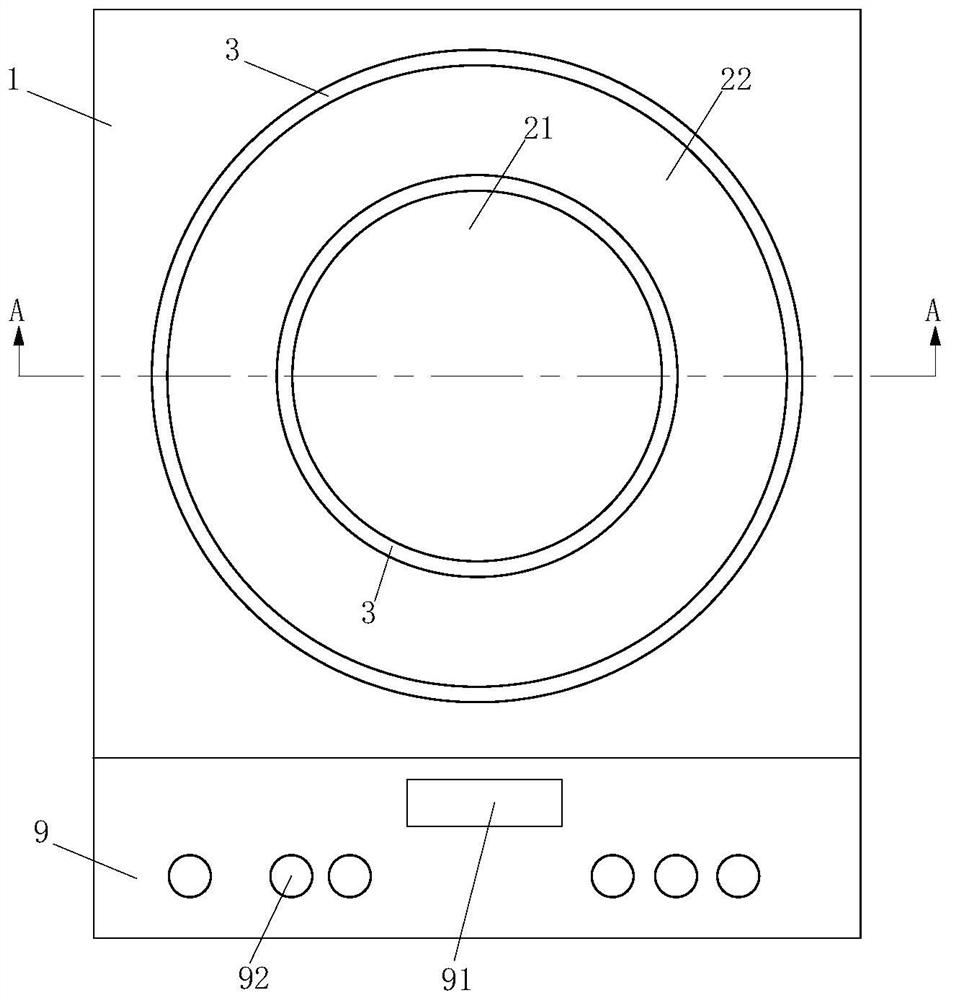
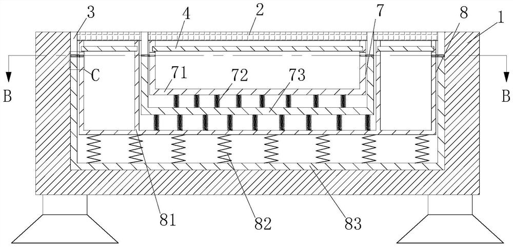
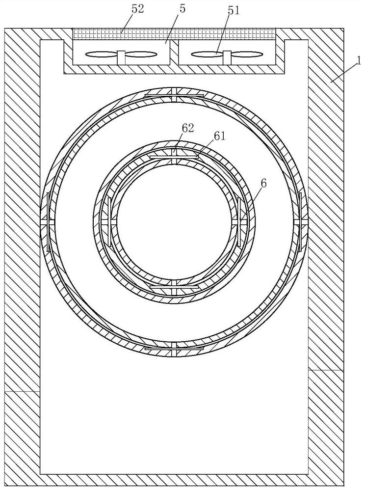
[0028] The technical solutions of the present invention will be further described below in conjunction with the accompanying drawings and through specific implementation methods. Wherein, the accompanying drawings are only for illustrative purposes, showing only schematic diagrams, rather than physical drawings, and should not be construed as limitations on this patent; in order to better illustrate the embodiments of the present invention, some parts of the accompanying drawings will be omitted, Enlargement or reduction does not represent the size of the actual product; for those skilled in the art, it is understandable that certain known structures and their descriptions in the drawings may be omitted.

[0029] In the drawings of the embodiments of the present invention, the same or similar symbols correspond to the same or similar components; , "inner", "outer" and other indicated orientations or positional relationships are based on the orientations or positional relations...


PUM


Abstract

The invention relates to the field of kitchen appliances, in particular to an anti-radiation induction cooker. The anti-radiation induction cooker comprises a cooker body, wherein a control system is arranged on the upper surface of the front end of the cooker body; a heat dissipation device is arranged on the inner wall of the rear end of the cooker body; a black quartz plate is arranged at the center of the upper surface of the cooker body; an anti-radiation ring is arranged on a side surface of the black quartz plate; a first supporting device and a second supporting device are arranged at the lower ends of the black quartz plate and the anti-radiation ring; heating coils are arranged at the upper ends of the interiors of the first supporting device and the second supporting device; and lever mechanisms are rotationally arranged in the first supporting device and the second supporting device. According to the anti-radiation induction cooker, a proper heating area can be selected according to the size of a used cooker, so that the waste of electric energy is reduced; and meanwhile, the extended anti-radiation ring can shield radiation and can also position the cooker, so that the cooker cannot slide out of an effective heating area.

Description

technical field [0001] The invention relates to the field of kitchen appliances, in particular to a radiation-proof electromagnetic cooker. Background technique [0002] Induction cooker is also known as induction cooker. In 1957, the first household induction cooker was born in Germany. In 1972, the United States began to produce induction cookers, and in the early 1980s, induction cookers began to sell well in Europe, America and Japan. The principle of the induction cooker is the phenomenon of electromagnetic induction, that is, the use of alternating current to pass through the coil to generate an alternating magnetic field with a constantly changing direction, and an eddy current will appear inside the conductor in the alternating magnetic field (the reason can be referred to Faraday's law of electromagnetic induction). It is caused by the vortex electric field pushing the carrier in the conductor (the electrons in the pot are definitely not iron atoms); the Joule heat...

Claims


Application Information

Patent Timeline
Patent Type & Authority Applications(China)
IPC IPC(8): F24C7/06F24C7/08F24C15/00F24C15/10F24C15/36
CPCF24C7/067F24C7/082F24C15/36F24C15/10F24C15/006
Inventor 叶子豪张天予
Owner 叶子豪
Why Eureka
Try Eureka