Test equipment for detection of anti-collision performance of shell of energy automobile

A technology of automobile casing and test equipment, applied in the direction of measuring device, strength characteristics, instrument, etc., can solve the problems of cylinder damage, reducing impact energy of impact hammer, and failing to meet impact test requirements.

Pending Publication Date: 2021-12-03
芦海光
View PDF0 Cites 0 Cited by
  • Summary
  • Abstract
  • Description
  • Claims
  • Application Information

AI Technical Summary

Problems solved by technology

[0003] However, the impact devices currently on the market either use the electromagnet to directly absorb the impact hammer for impact testing, or directly use the cylinder to impact. The first type of test will have a process of magnetic force elimination. When the power is turned off to release the impact hammer, The electromagnet will exert an upward attractive force on the impact hamm

Method used


Image

  • Test equipment for detection of anti-collision performance of shell of energy automobile
  • Test equipment for detection of anti-collision performance of shell of energy automobile
  • Test equipment for detection of anti-collision performance of shell of energy automobile

Examples


Embodiment 1

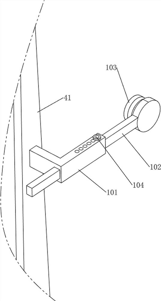
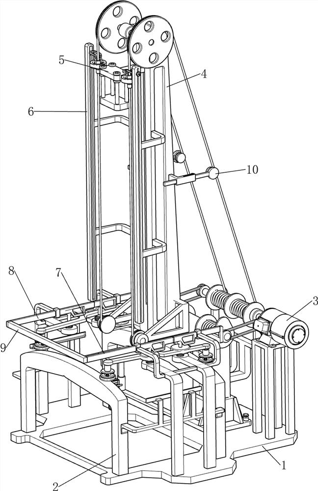
[0027] A test equipment for testing the anti-collision performance of the shell of targeted energy vehicles, such as Figure 1-4 As shown, it includes a base 1, a supporting platform 2, a motor 3, a pulling mechanism 4 and a pressing mechanism 5, the left side of the base 1 is provided with a supporting platform 2, the right front side of the base 1 is provided with a motor 3, and the output shaft of the base 1 and the motor 3 Pulling mechanism 4 is arranged between, and pulling mechanism 4 is provided with pressing mechanism 5, and pressing mechanism 5 comprises first sliding block 51, pressing block 52, pulling block 53, clamping block 54 and telescopic rod 55, pulls The parts of the mechanism 4 are slidably connected with a first sliding block 51, the bottom of the first sliding block 51 is provided with a detachable lower pressing block 52, and the parts of the pulling mechanism 4 are all provided with a pulling block 53, the front and rear of the first sliding block 51 Tw...

Embodiment 2

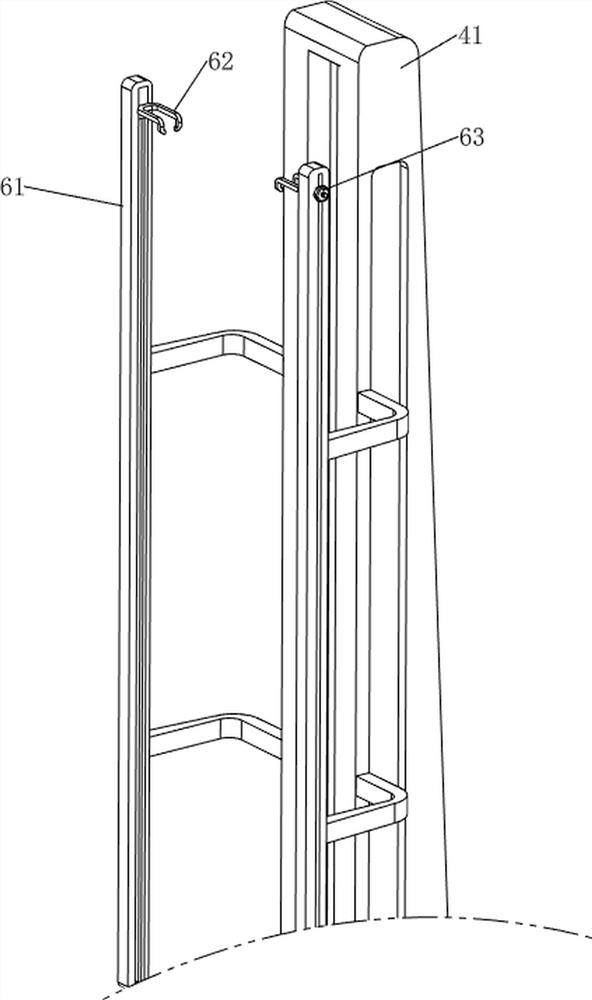
[0031] On the basis of Example 1, such as Figure 5-9 As shown, the distance adjustment mechanism 6 is also included, and the distance adjustment mechanism 6 includes a fixed rod 61, a second sliding block 62 and a fixed bolt 63. A second sliding block 62 is connected in a sliding manner, and a fixing bolt 63 is threadedly connected to the outside of the second sliding block 62 .

[0032] According to the degree of detection of the car shell, the fixing bolt 63 can be removed first, and then the second sliding block 62 can be moved up and down so that the second sliding block 62 can be moved to a suitable position, and then the fixing bolt 63 can be rotated and reset so that the second sliding block The block 62 is fixed, so that the height of the upward movement of the lower pressing block 52 can be adjusted. When the locking block 54 moves upwards and contacts the second sliding block 62, the locking block 54 is moved to the outside, and the lower pressing block 52 is moved do...


PUM


Abstract

The invention relates to the technical field of automobile part detection, in particular to test equipment for targeted detection of anti-collision performance of a shell of an energy automobile. The technical problem is to provide the test equipment for targeted detection of anti-collision performance of a shell of an energy automobile, which can realize automatic detection and has a fixing function. According to the technical scheme, the test equipment comprises a base, a supporting table, a motor, pulling mechanisms and a pressing mechanism, the supporting table is arranged on one side of the base, the motor is arranged on one side of the base, the pulling mechanisms are arranged between the base and an output shaft of the motor, and the pressing mechanism is arranged on the pulling mechanisms. Through cooperation of the distance adjusting mechanism, the pulling mechanism and the pressing mechanism, the detection height can be adjusted according to different types and different qualities of automobile shells, and the effect of automatic detection is achieved.

Description

technical field [0001] The invention relates to the technical field of automobile component detection, in particular to a testing device for detecting the anti-collision performance of the housing of a targeted energy automobile. Background technique [0002] With the continuous advancement of automobile technology, the car shell is the main body of driving safety. Its impact resistance directly affects the reliability of the protection level of the car shell. Whether the shell can pass the impact test and test the weak point of the shell protection is the shell protection. important indicators. [0003] However, the impact devices currently on the market either use the electromagnet to directly absorb the impact hammer for impact testing, or directly use the cylinder to impact. The first type of test will have a process of magnetic force elimination. When the power is turned off to release the impact hammer, The electromagnet will exert an upward attractive force on the im...

Claims


Application Information

Patent Timeline
IPC IPC(8): G01N3/303G01N3/06G01N3/04G01N3/02
CPCG01N3/303G01N3/04G01N3/062G01N3/02G01N2203/001G01N2203/0033G01N2203/0082G01N2203/0441G01N2203/0605G01N2203/0682
Inventor 芦海光
Owner 芦海光
Why Eureka
Try Eureka