Double flexible direct current unit power transmission system and power transmission mode switching method thereof

A power transmission system and mode switching technology, applied in the field of power transmission and distribution, can solve the problems of increasing the operating burden of operators and equipment, such as electrified shock, and achieve the effects of reducing switching complexity, avoiding blocking operations, and reducing operating burdens.

Pending Publication Date: 2021-12-03
GUANGDONG POWER GRID CO LTD +1
View PDF0 Cites 0 Cited by
  • Summary
  • Abstract
  • Description
  • Claims
  • Application Information

AI Technical Summary

Problems solved by technology

[0003] In a dual flexible DC transmission project, two flexible DC units are usually included to supply power to multiple AC systems at the rear end. When switching the transmission mode of the two flexible DC The direct unit is out of service, and the corresponding AC switch is re-operated to complete the switching of the power transmission mode. The whole process requires locking, charging, unlocking and other operations on the flexible direct unit, which increases the operating burden of the operator and the live shock of the equipment.

Method used


Image

  • Double flexible direct current unit power transmission system and power transmission mode switching method thereof
  • Double flexible direct current unit power transmission system and power transmission mode switching method thereof
  • Double flexible direct current unit power transmission system and power transmission mode switching method thereof

Examples


Embodiment Construction

[0040] The present invention will be further described in detail below in conjunction with the accompanying drawings and embodiments. It should be understood that the specific embodiments described here are only used to explain the present invention, but not to limit the present invention. In addition, it should be noted that, for the convenience of description, only some structures related to the present invention are shown in the drawings but not all structures.

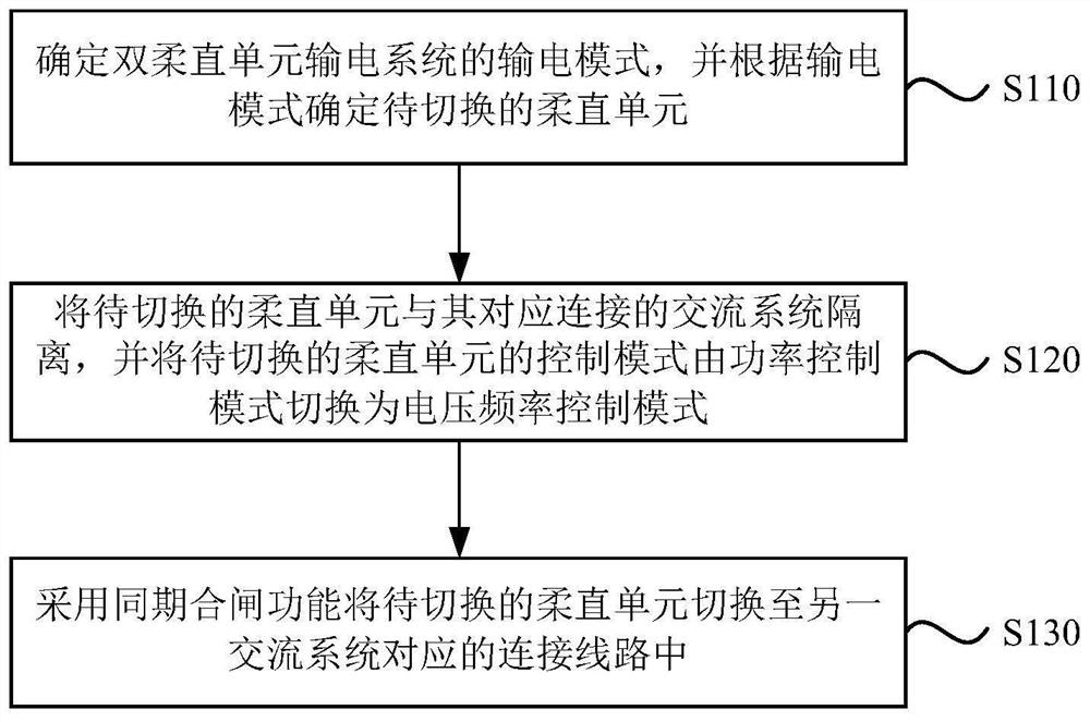
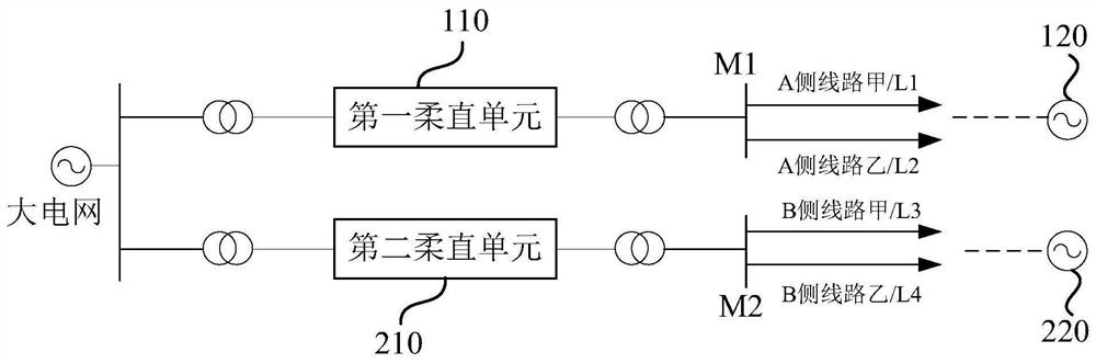
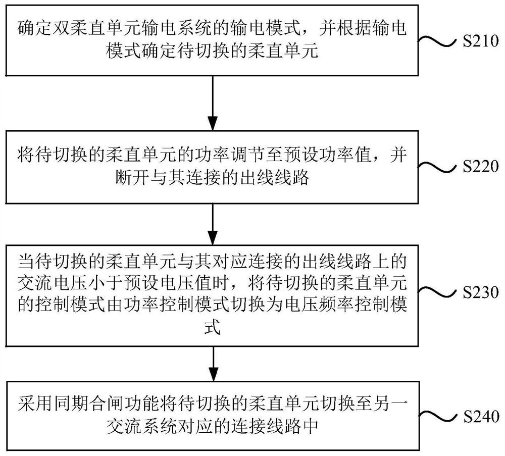
[0041] figure 1 It is a flow chart of a transmission mode switching method for a dual-flexible direct-unit power transmission system provided by the present invention, figure 2 For the structural schematic diagram of a kind of double flexible direct unit power transmission system provided by the present invention, refer to figure 1 with figure 2 , the power transmission mode switching method of the double flexible direct unit power transmission system provided by the present invention includes:

[0042] S110....


PUM


Abstract

The invention discloses a double flexible direct current unit power transmission system and a power transmission mode switching method thereof. The switching method comprises the following steps: determining a power transmission mode of the double flexible direct current unit power transmission system, and determining a to-be-switched flexible direct current unit according to the power transmission mode, wherein the power transmission mode comprises a distribution mode and a combined transmission mode; isolating the flexible direct current unit to be switched from an alternating current system correspondingly connected with the flexible direct current unit, and switching the control mode of the flexible direct current unit to be switched from a power control mode to a voltage frequency control mode; and switching the flexible direct current unit to be switched to a connecting line corresponding to another alternating current system by adopting a synchronous switching-on function. Compared with the prior art, the technical scheme provided by the invention can realize on-line switching of the power transmission mode of the double-flexible direct-current unit power transmission system, avoids locking operation on the flexible direct-current units, and is beneficial to reducing the switching complexity, so that the operation efficiency of an operator can be improved, and the operation burden of the operator is reduced.

Description

technical field [0001] Embodiments of the present invention relate to the technical field of power transmission and distribution, and in particular, to a power transmission system with dual flexible DC units and a method for switching power transmission modes. Background technique [0002] With the rapid development of power grid technology, the safety and reliability of the power grid system has become the top priority. [0003] In a dual flexible DC transmission project, two flexible DC units are usually included to supply power to multiple AC systems at the rear end. When switching the transmission mode of the two flexible DC The DC unit is out of service, and the corresponding AC switch is re-operated to complete the switching of the power transmission mode. The whole process requires operations such as locking, charging, and unlocking of the DC unit, which increases the operating burden of the operator and the live shock of the equipment. Contents of the invention ...

Claims


Application Information

Patent Timeline
IPC IPC(8): H02J9/06H02J1/10H02J3/36
CPCH02J9/062H02J1/10H02J3/36Y02E60/60
Inventor 魏志文潘维曾伟梁伟锋
Owner GUANGDONG POWER GRID CO LTD
Why Eureka
Try Eureka