Adjustable steel pipe pile interior anti-corrosion spraying device convenient to store and uniform in spraying
An anti-corrosion spraying and adjustable technology, which is applied in spraying devices, spray booths, etc., can solve problems such as difficult spray gun rotation, poor anti-corrosion spraying effect, and small force on the spray gun, so as to reduce labor intensity, ensure spray uniformity, and ensure stability sexual effect
- Summary
- Abstract
- Description
- Claims
- Application Information
AI Technical Summary
Problems solved by technology
Method used
Image

Examples
Embodiment 1
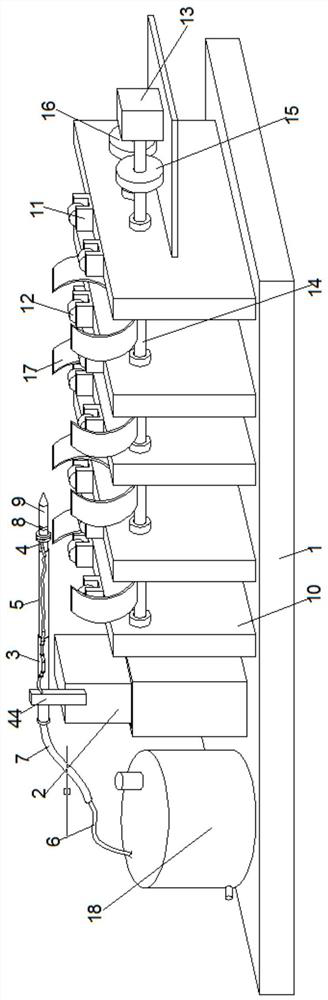
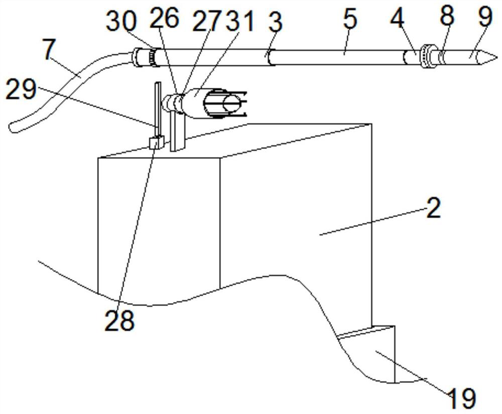
[0034] see Figure 1-8 , according to an embodiment of the present invention, an anti-corrosion spraying device for steel pipe piles that is convenient for storing and spraying uniformly and adjustable inside, includes a base 1, the top of the base 1 is connected with a connecting rod 2 through a lifting mechanism, and the connecting rod 2 is rotated The mechanism is equipped with a spray gun, and the spray gun includes a high-pressure pipe group, a compression rod group and a spray gun group, and the compression rod group includes a first telescopic part 3 and a second telescopic part 4, and the first telescopic part 3 and the second telescopic part A driving cylinder 5 is arranged between the telescoping parts 4, and the high-pressure pipe group includes a first high-pressure pipe 6 and a second high-pressure pipe 7, and the first high-pressure pipe 6 and the second high-pressure pipe 7 are connected, and the The second high-pressure pipe 7 is connected to the first telescop...
Embodiment 2
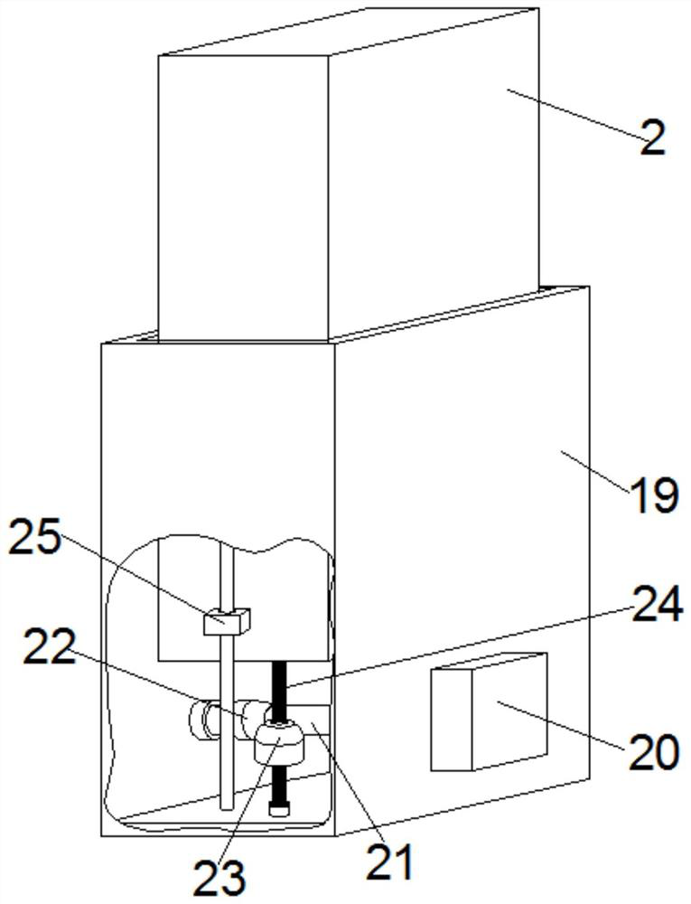
[0036] Such as figure 2 and Figure 4 As shown, the lifting mechanism includes a setting cylinder 19 fixed on the top of the base 1, a rotating motor 20 is provided on one side of the outer wall of the setting cylinder 19, and a rotating rod 21 is provided at the output end of the rotating motor 20. The other end of the rotating rod 21 is provided with an auxiliary bearing fixed on the inner wall of the setting cylinder 19, and the outer surface of the rotating rod 21 is fixedly covered with a first bevel gear 22, and the first bevel gear 22 is meshed with a The second bevel gear 23, the second bevel gear 23 is provided with a screw rod 24 penetratingly, and the inside of the connecting rod 2 is provided with a threaded groove matching the screw rod 24, and the connecting rod 2 is inserted into the Inside the setting cylinder 19, a sleeve 25 is fixedly arranged on the outer wall of the connecting rod 2, and a sleeve rod penetrating through the sleeve 25 is fixedly installed ...
Embodiment 3
[0040] Such as Figure 7-8 As shown, the material box 18 is circular, and the cleaning mechanism includes a cleaning motor 35 fixed on the top of the material box 18, and the cleaning motor 35 is fixedly provided with a cleaning rotating rod positioned at the inside of the material box 18 , the outer surface of the cleaning rotating rod is connected with a hanging plate 36 through a thin rod, the hanging plate 36 is arranged in contact with the inside of the material box 18, and the bottom of the cleaning rotating rod is fixedly provided with a bottom cleaning hanging plate 37, The bottom cleaning hanging plate 37 is an S-shaped structure, the bottom of the bottom cleaning hanging plate 37 is arranged in contact with the inner bottom of the material box 18, and the sound-absorbing mechanism is a sound-absorbing box 38, and the inner wall of the sound-absorbing box 38 is pasted with Sound insulation cotton, the sound-absorbing box 38 is fixed on the motor base, the positive and...
PUM
 Abstract
Description
Claims
Application Information
 - R&D
- Intellectual Property
- Life Sciences
- Materials
- Tech Scout
- Unparalleled Data Quality
- Higher Quality Content
- 60% Fewer Hallucinations
Browse by: Latest US Patents, China's latest patents, Technical Efficacy Thesaurus, Application Domain, Technology Topic, Popular Technical Reports.
© 2025 PatSnap. All rights reserved.Legal|Privacy policy|Modern Slavery Act Transparency Statement|Sitemap|About US| Contact US: help@patsnap.com