
A laser welding machine

A technology of laser welding machine and welding mechanism, applied in laser welding equipment, welding equipment, welding equipment and other directions, can solve problems such as low work efficiency, and achieve the effect of improving welding efficiency, convenience and speed.

Active Publication Date: 2022-03-15
浙江朗森智能科技有限公司
View PDF5 Cites 0 Cited by
  • Summary
  • Abstract
  • Description
  • Claims
  • Application Information

AI Technical Summary

Problems solved by technology

[0004] In view of the above-mentioned related technologies, the inventor believes that the cylinder is used for shaping and clamping. Since the corresponding speed of the cylinder is relatively slow and the clamping stability needs to be ensured, usually only 1-2 terminals can be completed within 1 second during the processing process. Welding work, its work efficiency is relatively low

Method used


Image

  • A laser welding machine
  • A laser welding machine
  • A laser welding machine

Examples


Embodiment Construction

[0050] The following is attached Figure 1-9 The application is described in further detail.

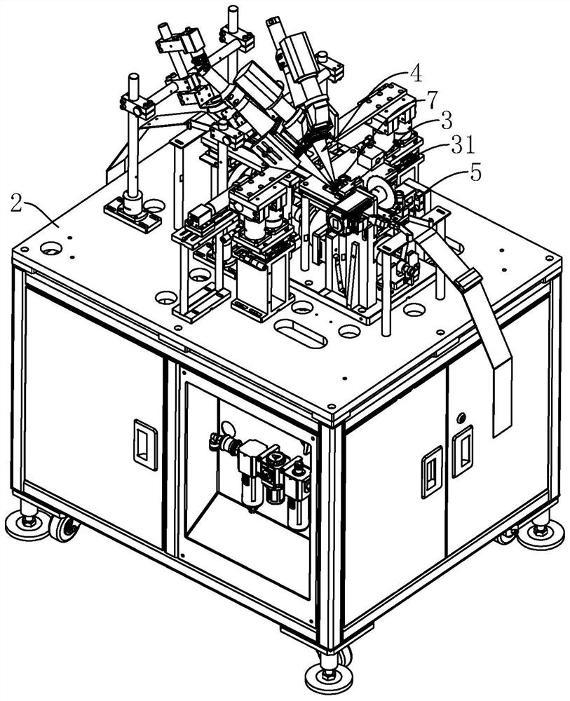
[0051] The embodiment of the application discloses a laser welding machine. refer to figure 2 , The laser welding machine includes a workbench 2, on which a plastic clamping mechanism 3 and a welding mechanism 4 are fixedly connected, and on the workbench 2, a material channel 5 for conveying terminals is fixed on the workbench 2 by installing a column frame. Wherein, there are two welding mechanisms 4 and they are respectively arranged on both sides of the forehearth 5 .

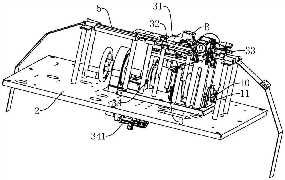
[0052] refer to figure 2 , image 3 The shaping and clamping mechanism 3 includes an upper cover 31 arranged on the workbench 2, a clamping assembly 32, a lifting assembly 33 and a drive center assembly 34, the clamping assembly 32 is set to two, and the upper cover 31 is arranged on the material channel 5 above.

[0053] The driving central component 34 is linked with the clamping component 32 and the lif...


PUM


Abstract

This application relates to a laser welding machine, including a workbench, a shaping and clamping mechanism and a welding mechanism arranged on the workbench. The workbench is provided with a feeding channel for conveying terminals, and there are two welding mechanisms respectively arranged on the feeding channel. On both sides, the shaping and clamping mechanism includes an upper cover plate, which is arranged above the material channel, and the upper cover plate is penetrated with an operation hole; two clamping components are provided, which can slide close to each other on the B surface and the D surface of the terminal. surface clamping and shaping; the lifting component, which drives the clamping component to move upwards so that the upper cover and the clamping component clamp and shape the A and C sides of the terminal; the drive center component drives the lifting component and the two clamping components synchronously Work: The driving shaft is driven to rotate by means of rotation. This application adopts the means of rotation to link each component, and the corresponding speed is fast and the degree of cooperation is high, which can effectively improve the welding efficiency.

Description

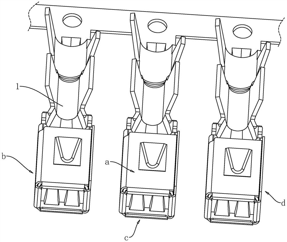
technical field [0001] The present application relates to the technical field of terminal processing, in particular to a laser welding machine. Background technique [0002] refer to figure 1 , is a terminal material strip in the related art, wherein each terminal 1 includes an inserting part and a connecting part obtained by integral stamping, the inserting part is a square structure formed by bending, and the side walls around the inserting part are respectively A surface a, B surface b, C surface c, and D surface d, wherein there is a gap formed by bending between the A surface a and the D surface d. In the follow-up, the gap needs to be welded to ensure the stability of the subsequent use of the product. During welding, it is necessary to use a shaping and clamping mechanism to shape and fix the side walls around the insertion part to ensure smooth welding. [0003] In the related art, the shaping and clamping mechanism usually uses a cylinder to squeeze and clamp the ...

Claims


Application Information

Patent Timeline
Patent Type & Authority Patents(China)
IPC IPC(8): B23K26/21B23K26/08B23K26/70B23K37/04
CPCB23K26/21B23K26/0853B23K26/0884B23K26/702B23K37/0443
Inventor 郭伟杜冰
Owner 浙江朗森智能科技有限公司
Learn More