Building environment monitoring device based on Internet of Things
An environmental monitoring and Internet of Things technology, which is applied to measuring devices, measuring instrument components, and cleaning methods using tools, etc., can solve the problem that monitoring equipment cannot be protected, the surface of the monitor cannot be removed autonomously, and the environmental monitoring around the construction site is affected. problems, etc., to ensure the effect of cleaning
- Summary
- Abstract
- Description
- Claims
- Application Information
AI Technical Summary
Problems solved by technology
Method used
Image
Examples
Embodiment 1
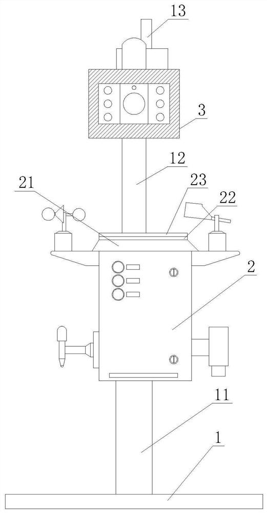
[0042] Such as Figure 1-7 As shown, the present invention provides a building environment monitoring device based on the Internet of Things, including a fixed mechanism 1 and a detection device body 2, the upper end of the fixed mechanism 1 is provided with a detection device body 2, and the top end of the fixed mechanism 1 is provided with a monitor 3 , the monitor 3 is arranged above the detection device body 2 .
[0043]In this embodiment, through the setting of the fixing mechanism 1, the entire monitoring equipment can be supported to ensure that the entire equipment can be used normally, and through the setting of the detection equipment body 2, all detection data can be recorded, saved and transmitted , thereby ensuring the real-time performance of the detection data, and then using the setting of the monitor 3, the surrounding environment of the construction site can be monitored, and when an emergency occurs, timely processing can be carried out.
Embodiment 2
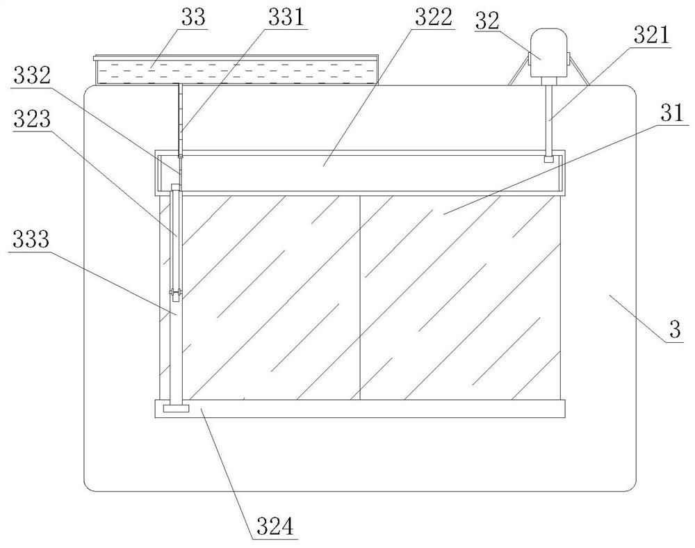
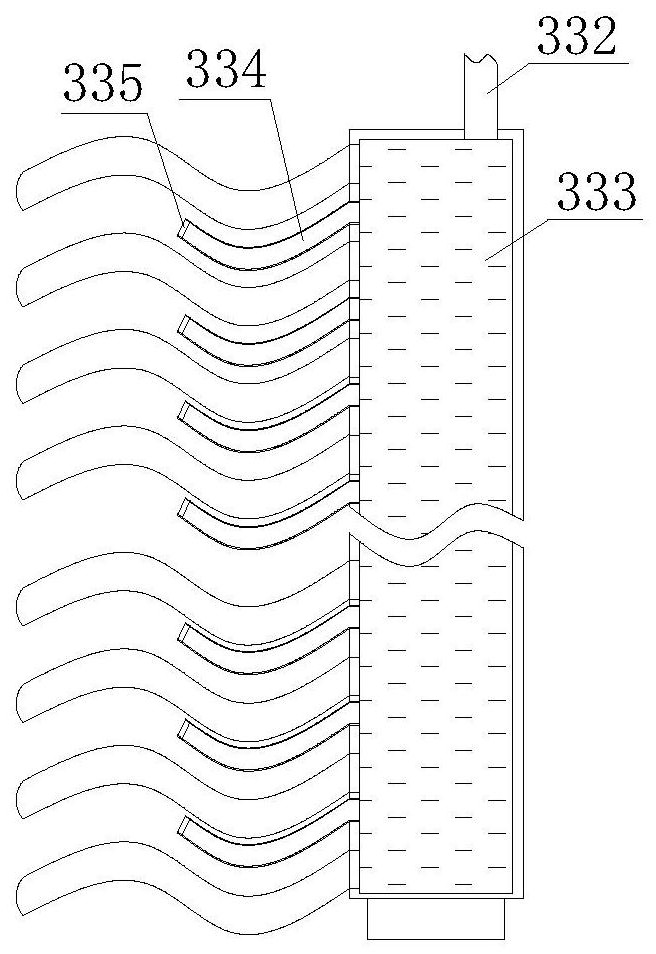
[0045] Such as Figure 1-7 As shown, on the basis of Embodiment 1, the present invention provides a technical solution: preferably, the monitor 3 includes a dust removal brush 333, and the dust removal brush 333 is arranged on the outer surface of the monitor 3, and the front of the monitor 3 is arranged There is a display screen 31, and the upper end of the monitor 3 is fixedly connected with a power box 32, and the upper end of the monitor 3 is fixedly connected with a dust removal water tank 33, and the power box 32 is arranged on one side of the dust removal water tank 33, and the output end of the power box 32 is movable Connected with output shaft 321, the front of monitor 3 is provided with No. 1 movable groove 322, and the lower end of output shaft 321 is arranged on the inside of No. 1 movable groove 322, and the inside of No. 1 movable groove 322 is connected with cleaning rod 323, monitor No. 2 movable groove 324 is arranged on the front of 3, and No. 1 movable groo...
Embodiment 3
[0048] Such as Figure 1-7 As shown, on the basis of Embodiment 1, the present invention provides a technical solution: preferably, the upper surface of the detection device body 2 is provided with a buffer mechanism 23, and the upper surface of the buffer mechanism 23 is provided with a No. 1 buffer plate 231, and the detection device The upper end of the body 2 is provided with a detection cabinet top 21, the upper end of the detection cabinet top 21 is fixedly connected with a connection block 22, the upper end of the connection block 22 is fixedly connected with the lower end of the buffer mechanism 23, and the lower end of the No. 1 buffer plate 231 is movably connected with a connection plate 233, the lower end of connecting plate 233 is movably connected with No. 2 buffer plate 232, and the lower end of connecting plate 233 is fixedly connected with No. 3 buffer spring 234, and No. 3 buffer spring 234 is arranged on the both sides of connecting plate 233, and the lower e...
PUM
 Abstract
Description
Claims
Application Information
 - R&D
- Intellectual Property
- Life Sciences
- Materials
- Tech Scout
- Unparalleled Data Quality
- Higher Quality Content
- 60% Fewer Hallucinations
Browse by: Latest US Patents, China's latest patents, Technical Efficacy Thesaurus, Application Domain, Technology Topic, Popular Technical Reports.
© 2025 PatSnap. All rights reserved.Legal|Privacy policy|Modern Slavery Act Transparency Statement|Sitemap|About US| Contact US: help@patsnap.com


