Simulation device for sea fog polarization transmission and test method thereof
A simulation device, sea fog technology, applied in the field of sea fog polarization transmission simulation device, can solve the problems of large error, fast fog dissipation, unstable sea fog simulation device, etc., achieve reliable technical support and improve accuracy
- Summary
- Abstract
- Description
- Claims
- Application Information
AI Technical Summary
Problems solved by technology
Method used
Image

Examples
Embodiment Construction
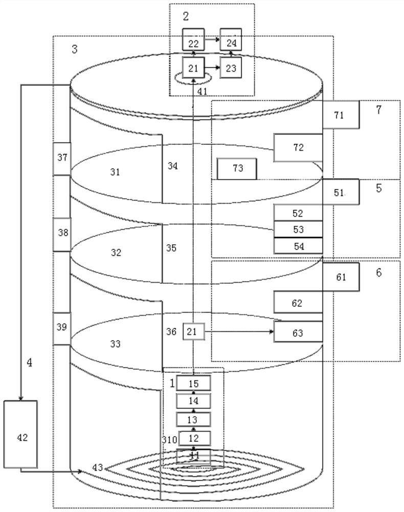
[0036] A simulation setup for polarization transmission in sea fog such as figure 1 As shown, it includes a transmitting device 1, a receiving device 2, a main box 3, an automatic light alignment system 4, a water mist layer calibration system 5, a salt spray layer calibration system 6, and an aerosol layer calibration system 7. Wherein the inside of the main box body 3 is horizontally provided with an aerosol layer lens partition 31, a water mist layer lens partition 32 and a salt mist layer lens partition 33 successively from top to bottom, and the inside of the main box body 3 is arranged from top to bottom. Divided into an aerosol layer, a water mist layer, a salt mist layer and an empty layer, the side wall of the aerosol layer is provided with a first observation window 34 and a first exhaust port 37, and the side wall of the salt mist layer is provided with a second observation window 35 and the second exhaust port 38, the side wall of the salt mist layer is provided wi...
PUM
 Abstract
Description
Claims
Application Information
 - Generate Ideas
- Intellectual Property
- Life Sciences
- Materials
- Tech Scout
- Unparalleled Data Quality
- Higher Quality Content
- 60% Fewer Hallucinations
Browse by: Latest US Patents, China's latest patents, Technical Efficacy Thesaurus, Application Domain, Technology Topic, Popular Technical Reports.
© 2025 PatSnap. All rights reserved.Legal|Privacy policy|Modern Slavery Act Transparency Statement|Sitemap|About US| Contact US: help@patsnap.com