
Antenna detection method and device, electronic equipment and storage medium

A detection method and antenna technology, applied in the field of communication, can solve problems such as poor signal, poor signal of mobile phone or mobile device, affecting the accuracy of detection results, etc.

Active Publication Date: 2021-12-07
SHANGHAI WINGTECH INFORMATION TECH CO LTD
View PDF22 Cites 1 Cited by
  • Summary
  • Abstract
  • Description
  • Claims
  • Application Information

AI Technical Summary

Problems solved by technology

If the antenna is not well connected during the production process, then when the mobile phone or various mobile devices with antennas are in the hands of the user, various signal problems will occur
In addition, if the antenna connection is detected to be good during the antenna production process, but the installed antenna cannot receive radio frequency signals in certain frequency bands, the mobile phone or mobile device signal will also be poor. Therefore, the inspection of the production line must not only detect Whether the antenna is well connected, and whether the antenna can receive radio frequency signals of different frequency bands
[0003] The antenna detection method in the prior art is to place a mobile phone or other terminal equipment with an antenna next to an antenna coupling plate, and then transmit a radio frequency signal from the antenna in the mobile phone or other terminal equipment with an antenna, and view it through the antenna coupling plate. Whether the power value on the meter of the coupling board is within a reasonable range is used to judge whether the antenna in the mobile phone or other terminal equipment with an antenna is well connected or whether the antenna can receive radio frequency signals of different frequency bands, but this method is very easy There is external interference, and when there is a deviation in the position of the coupling plate, it will affect the accuracy of the detection result

Method used


Image

  • Antenna detection method and device, electronic equipment and storage medium
  • Antenna detection method and device, electronic equipment and storage medium
  • Antenna detection method and device, electronic equipment and storage medium

Examples


Embodiment Construction

[0061] In order to more clearly understand the above objects, features and advantages of the present disclosure, the solutions of the present disclosure will be further described below. It should be noted that, in the case of no conflict, the embodiments of the present disclosure and the features in the embodiments can be combined with each other.

[0062] In the following description, many specific details are set forth in order to fully understand the present disclosure, but the present disclosure can also be implemented in other ways than described here; obviously, the embodiments in the description are only some of the embodiments of the present disclosure, and Not all examples.

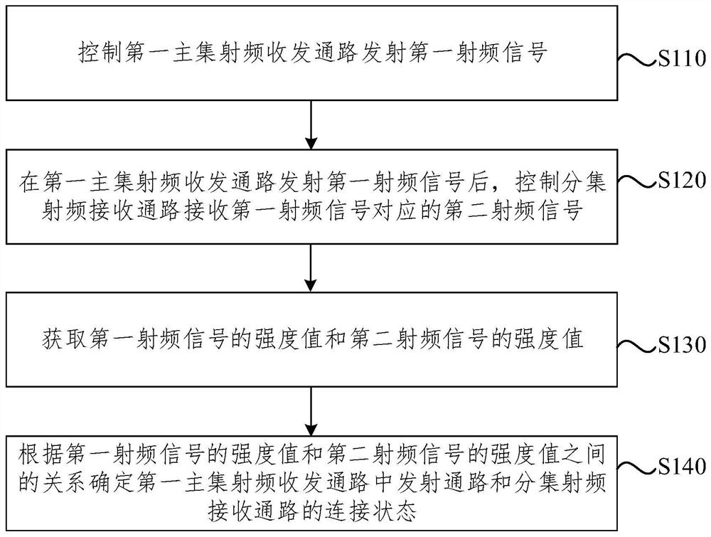
[0063] figure 1 It is a schematic flowchart of an antenna detection method provided by an embodiment of the present disclosure. This embodiment is applicable to the situation of detecting the connection state of the antenna during the production process. The method in this embodiment can be ex...


PUM


Abstract

The invention relates to an antenna detection method and device, electronic equipment and a storage medium. In a radio frequency circuit, a radio frequency transceiver, a first power amplifier, a first duplexer, a first master set switch and a first master set antenna form a first master set radio frequency transceiving path, and a diversity antenna, a diversity switch and the radio frequency transceiver form a diversity radio frequency receiving path. The method comprises the following steps: controlling a first main set radio frequency transceiving path to transmit a first radio frequency signal; after the first main set radio frequency receiving and transmitting path transmits a first radio frequency signal, controlling the diversity radio frequency receiving path to receive a second radio frequency signal corresponding to the first radio frequency signal; acquiring an intensity value of the first radio frequency signal and an intensity value of the second radio frequency signal; and according to the relationship between the intensity value of the first radio frequency signal and the intensity value of the second radio frequency signal, determining the connection state of the transmitting path and the diversity radio frequency receiving path in the first main set radio frequency receiving and transmitting path, and improving the accuracy of an antenna detection result.

Description

technical field [0001] The present disclosure relates to the technical field of communications, and in particular, to an antenna detection method, device, electronic equipment, and storage medium. Background technique [0002] Current terminal devices, such as mobile phones or various mobile devices with antennas, need to detect the antennas during the production process, and determine whether the antennas are well connected through the detection of the antennas. If the antenna is not well connected during the production process, then when the mobile phone or various mobile devices with antennas are in the hands of the user, various signal problems will occur. In addition, if the antenna connection is detected to be good during the antenna production process, but the installed antenna cannot receive radio frequency signals in certain frequency bands, the mobile phone or mobile device signal will also be poor. Therefore, the inspection of the production line must not only det...

Claims


Application Information

Patent Timeline
Patent Type & Authority Applications(China)
IPC IPC(8): H04B1/40H04B1/401H04B17/10H04B17/20
CPCH04B1/40H04B1/401H04B17/101H04B17/20Y02D30/70
Inventor 何文卿
Owner SHANGHAI WINGTECH INFORMATION TECH CO LTD
Features
  • Generate Ideas
  • Intellectual Property
  • Life Sciences
  • Materials
  • Tech Scout
  • Unparalleled Data Quality
  • Higher Quality Content
  • 60% Fewer Hallucinations
Learn More