Anesthesia cabin with waste gas recovery effect for anesthesia room

A waste gas recovery, anesthesia room technology, applied in veterinary instruments, medical science, dispersed particle separation, etc., can solve the problem of long time required for anesthesia, and achieve the effect of improving the effect

Inactive Publication Date: 2021-12-10
隆英泽
View PDF1 Cites 0 Cited by
  • Summary
  • Abstract
  • Description
  • Claims
  • Application Information

AI Technical Summary

Problems solved by technology

[0004] An anesthesia cabin that rapidly volatilizes anesthetics in the above-mentioned patent has the following disadvantages: when anesthetizing animals, the anesthesia cannot be inhaled by the animals quickly, which makes the time required for anesthesia longer

Method used


Image

  • Anesthesia cabin with waste gas recovery effect for anesthesia room
  • Anesthesia cabin with waste gas recovery effect for anesthesia room
  • Anesthesia cabin with waste gas recovery effect for anesthesia room

Examples


Embodiment 1

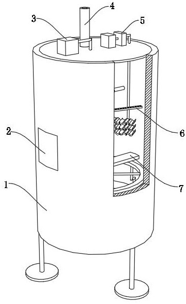
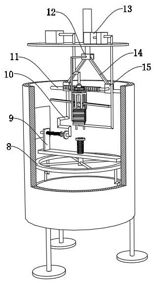
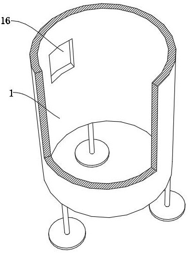
[0035] An anesthesia cabin for an anesthesia room with waste gas recovery effect, such as Figure 1-6As shown, it includes an anesthesia cabin main body 1, the inner wall of the arc surface of the anesthesia cabin main body 1 is fixed with a traverse column 11 by bolts, and the outer wall of the traverse column 11 is slidably connected with two sliding seats 15, and the anesthesia cabin main body 1 The outer wall of the top is fixed with an electric telescopic rod 4 by bolts, and the output end of the electric telescopic rod 4 is fixed with a lifting frame 12 by bolts, and the inner wall of the lifting frame 12 is rotatably connected with two connecting rods 14, and the two connecting rods 14 are away from One end of the lifting frame 12 is respectively rotatably connected to the inner walls of two sliding seats 15, wherein the outer wall of one side of the sliding seat 15 is fixed with a rack 21 by bolts, and the outer wall of the traverse column 11 is fixed with a guard plate...

Embodiment 2

[0041] An anesthesia cabin for an anesthesia room with waste gas recovery effect, such as Figure 1-5 As shown, in order to collect the exhaust gas produced in the anesthesia process; this embodiment makes the following supplements on the basis of embodiment 1: the outer wall of the top of the anesthesia cabin main body 1 is fixed with an adsorption stuffing box 5 and an exhaust fan 13 by bolts, and the The adsorption stuffing box 5 and the exhaust fan 13 are plugged and fixed through a hose, and one end of the adsorption stuffing box 5 is plugged into the bottom end of the guide hollow column 28 through a hose, and the exhaust fan 13 can be used to control the main body of the anesthesia cabin. 1, the anesthesia waste gas inside is sucked, and the sucked anesthesia waste gas can enter the interior of the adsorption stuffing box 5 through a hose for adsorption, so as to avoid air pollution caused by the residual anesthesia waste gas; the outer wall of the top of the guide hollo...


PUM


Abstract

The invention discloses an anesthesia cabin with a waste gas recovery effect for an anesthesia room, and relates to the technical field of anesthesia cabins for anesthesia rooms. The anesthesia effect is ensured; the anesthesia cabin comprises an anesthesia cabin body, a transverse moving column is arranged on the inner wall of the cambered surface of the anesthesia cabin body, two sliding seats are movably connected to the outer wall of the circumference of the transverse moving column, an electric telescopic rod is arranged on the outer wall of the top of the anesthesia cabin body, a lifting frame is arranged at the output end of the electric telescopic rod, and two connecting rods are movably connected to the inner wall of the lifting frame; the ends, away from the lifting frame, of the two connecting rods are movably connected to the inner walls of the two sliding seats correspondingly. By arranging the electric telescopic rod, the lifting frame can be controlled to move up and down, so that the two sliding seats horizontally slide in a reciprocating mode along the circumferential outer wall of the transverse moving column under the adjusting effect of the connecting rod, and therefore a rack can drive a gear to do clockwise and anticlockwise circumferential motion at a certain angle in the horizontal reciprocating motion process.

Description

technical field [0001] The invention relates to the technical field of anesthesia cabins for anesthesia rooms, in particular to an anesthesia cabin for anesthesia rooms with exhaust gas recovery effect. Background technique [0002] In the process of experimental research on animals, the animals need to be anesthetized. The traditional method is mainly to anesthetize the experimental animals by directly injecting anesthetics such as xylazine and pentobarbital. In order to ensure the effect of anesthesia, gas inhalation anesthesia technology is usually used, which can make animals quickly anesthetized and wake up quickly. It is easy to control the depth of anesthesia during operation and has good safety. When inhaling animals During anesthesia, in order to avoid the safety of the animals, an anesthesia cabin is usually set up, and the animals are placed in the anesthesia cabin for inhalation anesthesia. [0003] After searching, the Chinese patent application number is CN201...

Claims


Application Information

Patent Timeline
IPC IPC(8): A61D7/04B01D53/04
CPCA61D7/04B01D53/04
Inventor 隆英泽李新珍
Owner 隆英泽
Why Eureka
Try Eureka