Stay cable tensioning end anchorage device structure

A cable-stayed and tensioned technology, which is applied to bridge parts, bridges, buildings, etc., can solve the problems of steel strand corrosion and work safety, and achieve the effect of ensuring anti-corrosion and anti-rust performance and improving operation safety

Active Publication Date: 2021-12-10
CHINA RAILWAY 16TH BUREAU GRP 5TH ENG
View PDF12 Cites 0 Cited by
  • Summary
  • Abstract
  • Description
  • Claims
  • Application Information

AI Technical Summary

Problems solved by technology

In the existing cable tension end anchorage, the steel strand is provided with a protective cover for protection, but the protective cover is placed in the anchor hole, which will affect its work safety, and if the protective cover is stripped, the protective cover and the anchorage The strands at the holes are affected by corrosion

Method used


Image

  • Stay cable tensioning end anchorage device structure
  • Stay cable tensioning end anchorage device structure
  • Stay cable tensioning end anchorage device structure

Examples


Embodiment Construction

[0022] In order to make the object, technical solution and advantages of the present invention clearer, the present invention will be described in further detail below in conjunction with the drawings and embodiments; in the drawings or descriptions, similar or identical parts use the same symbols, and in actual In application, the shape, thickness or height of each part can be enlarged or reduced. The various embodiments listed in the present invention are only used to illustrate the present invention, and are not intended to limit the scope of the present invention. Any obvious modifications or changes made to the present invention do not depart from the spirit and scope of the present invention.

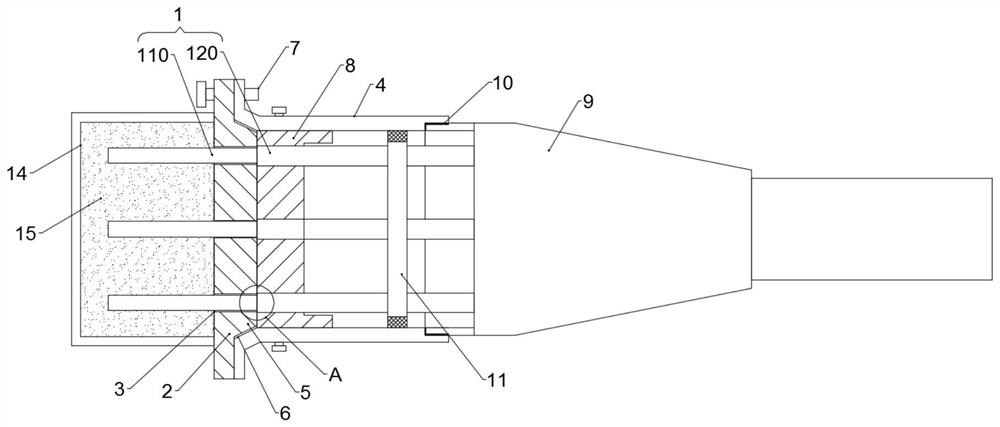
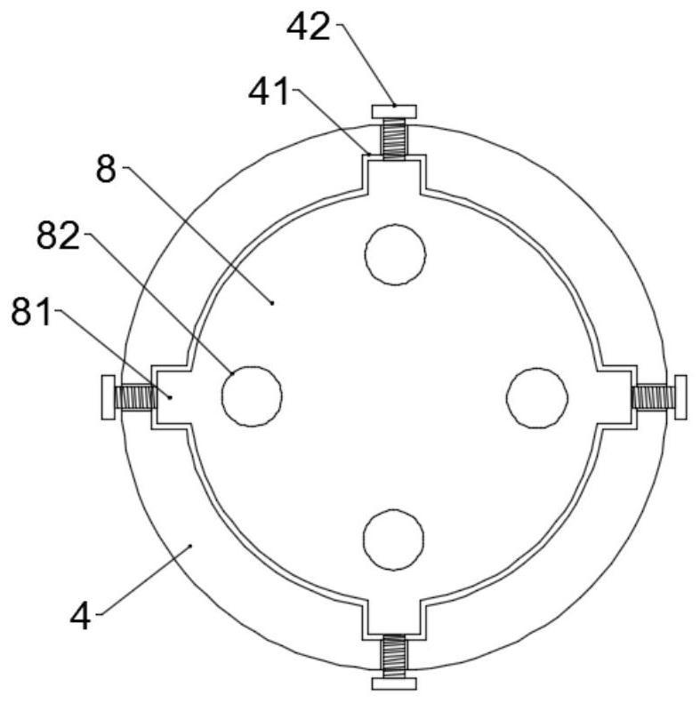
[0023] In one embodiment, such as figure 1 and figure 2 As shown, an anchorage structure at the tension end of a cable stay includes a traction cable 1, an anchor plate 2 and an anchor cup 4, the anchor cup 4 is connected to the internal reinforcement of the concrete girder, an...


PUM


Abstract

The invention discloses an anchorage device structure at a tensioning end of a stay cable. The anchorage device structure comprises a traction inhaul cable, an anchoring plate and an anchoring cup. The anchoring plate is arranged at one end of the anchoring cup, the side portion of the anchoring plate is connected with the side portion of the anchoring cup through a tension adjusting bolt, the traction inhaul cable comprises a steel strand, and the periphery of the steel strand is sleeved with an outer protection sleeve. The anchoring plate is provided with an anchoring hole for a traction inhaul cable to penetrate through, the fastening barrier plate is provided with a guide hole corresponding to the anchoring hole and allowing the traction inhaul cable to penetrate through, and the side of the guide hole and the side wall of the anchor cup are fastened in an axial adjusting mode. A blocking piece is arranged between the guide hole and the anchoring hole and used for preventing the outer protection sleeve from penetrating through the anchoring hole to extend to the other side of the anchoring plate. The anchorage device structure can prevent the outer protection sleeve from entering the anchoring hole to influence the operation safety, and the side, facing the anchoring hole from the blocking piece, of the traction inhaul cable is in an exposed state; therefore, the structure only needs to ensure the anti-corrosion performance of the blocking surface, so that the anti-corrosion and anti-rust performance of the exposed steel strand can be ensured, and the operation safety is improved.

Description

technical field [0001] The invention relates to the technical field of road and bridge construction anchors, in particular to an anchor structure at the tension end of a cable-stayed cable. Background technique [0002] A cable-stayed bridge is a bridge in which the main girder is directly pulled on the bridge tower by many cables. It is mainly composed of cable towers, main beams and stay cables. [0003] The stay cable anchor includes anchor end and tension end. The anchor end is set in the main box girder. Insert the anchor end of the cable into the anchor box of the box girder, install the steel support pad, and tighten the anchor bolt end to complete the installation. In the existing cable tension end anchorage, the steel strand is provided with a protective cover for protection, but the protective cover is placed in the anchor hole, which will affect its work safety, and if the protective cover is stripped, the protective cover and the anchorage The strands at the h...

Claims


Application Information

Patent Timeline
Patent Type & Authority Applications(China)
IPC IPC(8): E01D19/16
CPCE01D19/16
Inventor 张黎张旭东张志永魏冲秦金祥刘彬刘立伟
Owner CHINA RAILWAY 16TH BUREAU GRP 5TH ENG
Why Eureka
Try Eureka