Main arch support structure of overpass bridge and installation method

A technology of support structure and flyover bridge, applied in the direction of bridge, bridge parts, bridge construction, etc., to achieve good support effect

Pending Publication Date: 2021-12-10
CHINA FIRST HIGHWAY ENG
View PDF6 Cites 0 Cited by
  • Summary
  • Abstract
  • Description
  • Claims
  • Application Information

AI Technical Summary

Problems solved by technology

[0005] In order to solve the problem that the existing bracket may affect the splicing of the hoisted main arch split body and the installed main arch split body by the crane, this application provides a main arch bracket structure and installation method of a flyover bridge

Method used


Image

  • Main arch support structure of overpass bridge and installation method
  • Main arch support structure of overpass bridge and installation method
  • Main arch support structure of overpass bridge and installation method

Examples


Embodiment 1

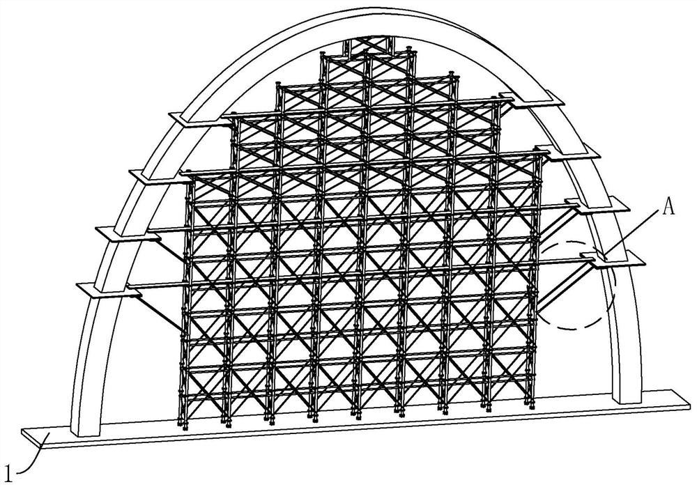
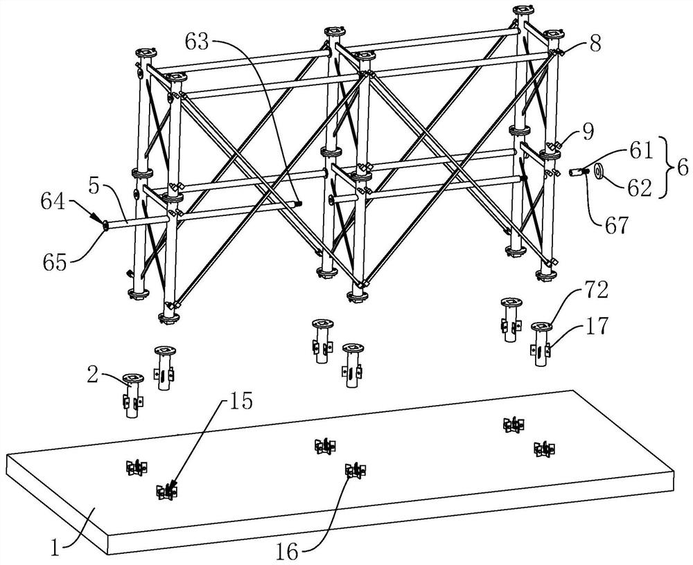
[0045] refer to figure 1 and figure 2 , a main arch support structure of a flyover bridge includes a support base plate 1 and several piles 2, the main arch is spliced ​​by several main arch splits, and the two main arches at the bottom of the main arch are separately fixed on the ground , the bracket bottom plate 1 is laid between the two main arch splits at the bottommost end of the main arch. The top of the support bottom plate 1 is provided with several installation grooves 15, and several installation grooves 15 are divided into two groups, and the two groups of installation grooves 15 are arranged at intervals along the width direction of the support bottom plate 1, and several installation grooves 15 in the same group are arranged along the width direction of the support bottom plate 1. The longitudinal direction of the support bottom plate 1 is evenly distributed. Several first limiting plates 16 are vertically arranged on the support bottom plate 1, and each mounti...

Embodiment 2

[0051] A method for installing a main arch support of a flyover bridge, comprising the steps of:

[0052] Fix the pile 2: place the support base plate 1 and fix the stake 2 on the support base plate 1.

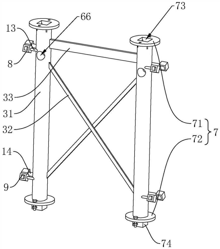
[0053] Install the bracket split 3: fix the bracket split 3 on the pile 2, and use the horizontal clamp column 5 to connect the bracket split 3 adjacent in the horizontal direction; the vertical height of the bracket split 3 is based on the existing height of the main arch. Depending on the building height, the building height of the support split body 3 is always lower than the building height of the main arch. According to the height of the main arch, more support split bodies 3 are connected at the top of the support split body 3 so as to facilitate pouring of the main arch.

[0054] The first inclined rod connected between the bracket splits 3 in the same horizontal direction is determined according to the angle between the main arch splits:

[0055] The four ends of the ...


PUM


Abstract

The invention relates to a main arch support structure of an overpass bridge and an installation method, wherein the main arch support structure comprises a support bottom plate, a plurality of piles and a plurality of support split bodies, the piles are vertically arranged at the top end of the support bottom plate, every two piles correspond to one support split body, and the top ends of the two piles are fixedly connected with the bottom ends of the support split bodies; the two first inclined clamping rods are arranged between the adjacent support split bodies in the same horizontal direction, the two first inclined clamping rods are arranged in a crossed mode, a horizontal clamping column is arranged between the adjacent support split bodies in the same horizontal direction in a penetrating mode, a fastening assembly is arranged on the horizontal clamping column, and a connecting assembly is arranged between the adjacent support split bodies in the same vertical direction. In the application, the main arch support is built according to the built height of a main arch, the horizontal clamping columns enable the support in the horizontal direction to be detachably installed in a split mode through the fastening assemblies, and the connecting assemblies enable the support in the vertical direction to be detachably installed in a split mode; therefore, the main arch support is prevented from influencing the effect that the crane moves the hoisted main arch split body to the installed main arch split body.

Description

technical field [0001] The present application relates to the field of overpass bridge construction, in particular to a main arch support structure and installation method of overpass bridges. Background technique [0002] The flyover is an upper-span facility across the road. It is usually set up at places where pedestrians, bicycles and other vehicles cross expressways and first-class roads, especially where traffic flow conflicts are serious, such as stations, large commercial centers or other intersections. A flyover bridge refers to a bridge that crosses traffic lines such as highways, railways or urban roads. Across the existing lines, it is divided into separated and intercommunicating. The former only ensures that the vehicles on the upper and lower lines can pass independently; the latter allows the vehicles on the upper and lower lines to pass through each other, and builds complex roundabout ramps on the plane and elevation, occupying a lot of land. [0003] At...

Claims


Application Information

Patent Timeline
IPC IPC(8): E01D21/00E01D19/00
CPCE01D21/00E01D19/00
Inventor 富铮王凯贾占峰张军康学峰王允志冯峰李阳
Owner CHINA FIRST HIGHWAY ENG
Why Eureka
Try Eureka