Electronic thickness gauge for laser application

An electronic thickness gauge and laser technology, applied in the direction of instruments, measuring devices, optical devices, etc., can solve the problems of inaccurate measurement, inconvenient detection of the object to be measured, inconvenient practical use, etc., and achieve the effect of avoiding movement

Active Publication Date: 2021-12-10
苏州曼德特光电技术有限公司
View PDF7 Cites 1 Cited by
  • Summary
  • Abstract
  • Description
  • Claims
  • Application Information

AI Technical Summary

Problems solved by technology

[0003] However, after searching, it is found that a Chinese patent with the authorized announcement number CN206919844U discloses a laser thickness gauge with a pressing platform. By setting a pressing platform on the body, some small waiting The thickness measurement of the measured object is convenient for the whole device to measure the thickness of some small objects to be measured; by setting the limit ring, the movement of the side rod in the vertical direction is limited, and the deviation of the side rod is prevented. The inaccurate measurement during measurement further improves the stability of the device during measurement and improves the accuracy of measurement; by setting the return spring, it facilitates the reset of the drive block after the movement, and further facilitates the use of the entire device. However, when When the thickness of each position of the object to be measured is different, it is not convenient to detect different positions of the object to be measured, which has certain limitations and is not convenient for practical use

Method used


Image

  • Electronic thickness gauge for laser application
  • Electronic thickness gauge for laser application
  • Electronic thickness gauge for laser application

Examples


Embodiment 1

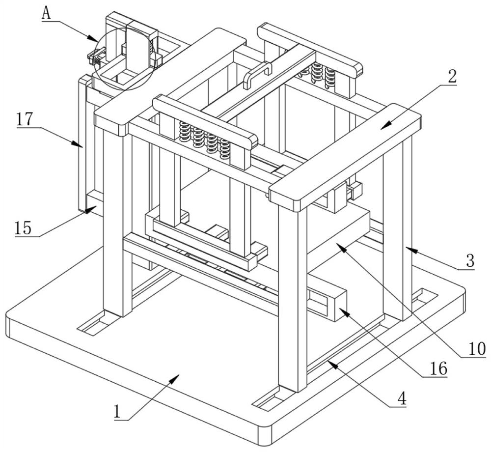
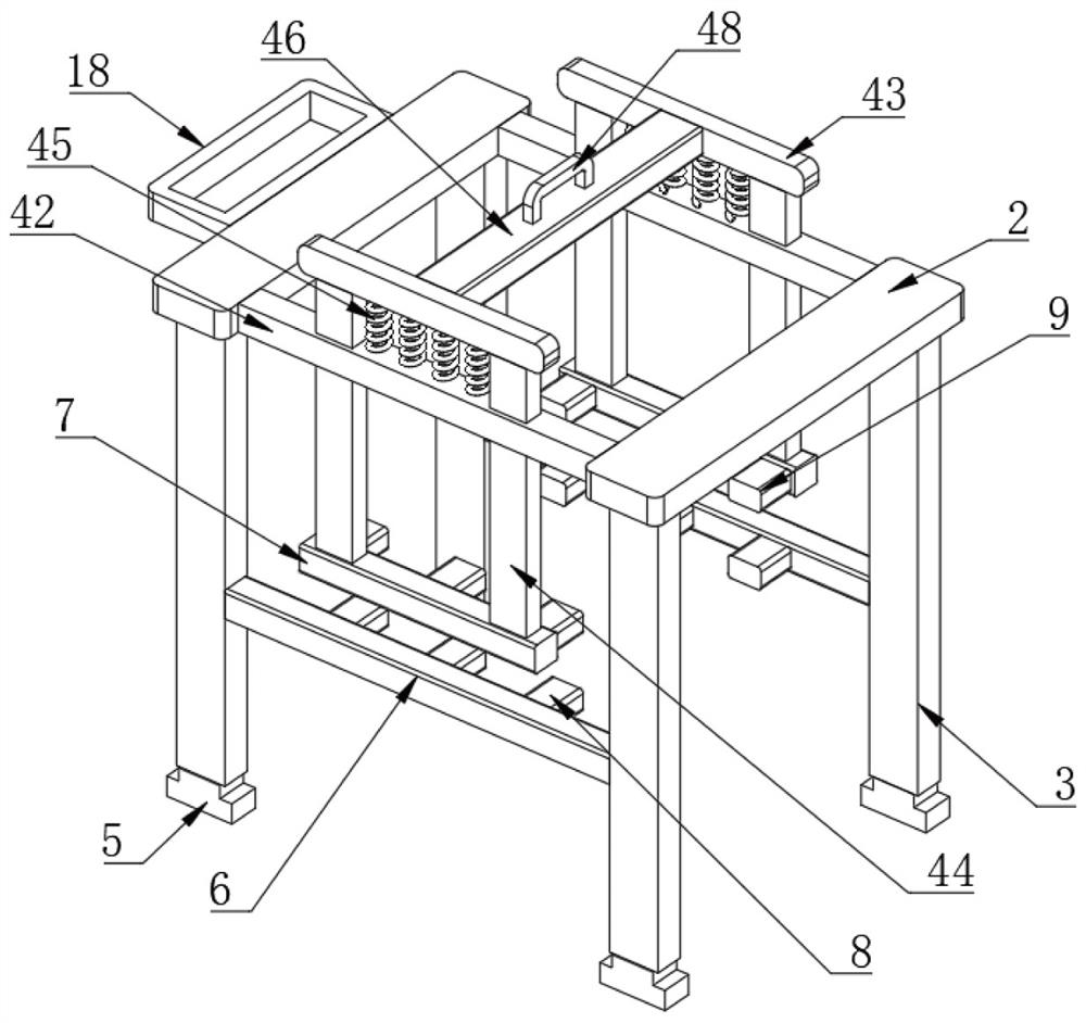
[0031] Such as Figure 1 to Figure 8 As shown, an electronic thickness gauge for laser application includes a base 1, two top plates 2 are arranged above the base 1, one side of one top plate 2 is fixedly connected with a first fixing ring 18, and the bottom of the top plate 2 is fixedly connected There are two first fixed columns 3, the bottom of the first fixed column 3 is fixedly connected with the first slider 5, the top of the base 1 is provided with two first slide grooves 4, and the top of the base 1 is provided with two first supports plate 6, the two ends of the first support plate 6 are respectively connected with the two first fixed columns 3, the object to be measured 10 is provided above the base 1, the first movable plate 7 is provided above the first support plate 6, and the first One side of the support plate 6 is fixedly connected with a plurality of supporting plates 8, and one side of the first movable plate 7 is fixedly connected with a plurality of first p...

Embodiment 2

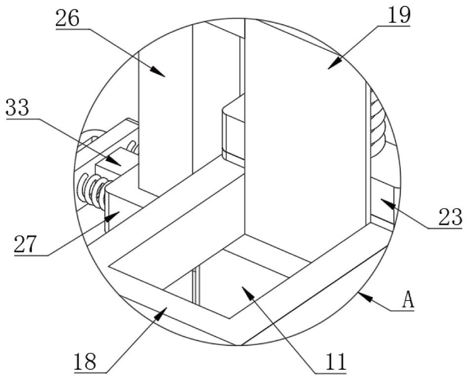
[0035] see Figure 1 to Figure 8 , where the same or corresponding components as those in Embodiment 1 use the corresponding reference numerals as in Embodiment 1, and for the sake of simplicity, only the differences from Embodiment 1 will be described below. The difference between this embodiment 2 and embodiment 1 is: please refer to figure 1 , image 3 , Figure 6 and Figure 8 , the fixed assembly includes a second connecting plate 25 arranged on one side of the lifting plate 19, the bottom of the second connecting plate 25 is fixedly connected with a second movable plate 26, and the second movable plate 26 is sheathed with a second fixed ring 27, One side of the second fixed ring 27 is fixedly connected with the first fixed plate 11, and the third fixed plate 28 is provided under the second movable plate 26, and one side of the third fixed plate 28 is fixedly connected with the first fixed plate 11, and the second fixed plate 28 is fixedly connected with the first fixe...

Embodiment 3

[0037] see Figure 1 to Figure 8 , where the same or corresponding components as those in Embodiment 1 use the corresponding reference numerals as in Embodiment 1, and for the sake of simplicity, only the differences from Embodiment 1 will be described below. The difference between this embodiment 3 and embodiment 1 is: please refer to Figure 6 and Figure 7 , the first elastic unit includes two second fixed columns 36 arranged in the second rectangular hole 22, both ends of the second fixed column 36 are fixedly connected with the inner wall of the second rectangular hole 22, and the outside of the second fixed column 36 A second compression spring 37 is sheathed, and the second compression spring 37 is located on the top of the second pressing plate 23. The second elastic unit includes a groove 38 opened at the bottom of the lifting plate 19, and a third movable plate is arranged in the groove 38. 39, the bottom of the third movable plate 39 is fixedly connected with the ...


PUM


Abstract

The invention discloses an electronic thickness gauge for laser application. Theelectronic thickness gauge comprises a base, two top plates are arranged above the base, one side of one top plate is fixedly connected with a first fixing ring, the bottom of the top plate is fixedly connected with two first fixing columns, and the bottoms of the first fixing columns are fixedly connected with first sliding blocks. Two first sliding grooves are formed in the top of the base, two first supporting plates are arranged above the base, the two ends of the first supporting plates are connected with the two first fixing columns respectively, an object to be measured is arranged above the base, a first movable plate is arranged above the first supporting plates, and a plurality of bearing plates are fixedly connected to one side of each first supporting plate; and one side of the first movable plate is fixedly connected with a plurality of first pressing plates. The invention relates to an electronic thickness gauge for laser application, belongs to the technical field of thickness measuring instruments, and aims to enable an object to be measured to move and enable a laser displacement sensor to move relative to the object to be measured so as to detect the thicknesses of different positions on the object to be measured.

Description

technical field [0001] The invention relates to the technical field of thickness measuring instruments, in particular to an electronic thickness measuring instrument for laser application. Background technique [0002] The laser thickness gauge is generally composed of two laser displacement sensors that shoot up and down. The upper and lower sensors measure the position of the upper surface and the lower surface of the measured object respectively, and the thickness of the measured object is obtained by calculation. The advantage of the laser thickness gauge is that it uses non-contact measurement, which is more accurate than the contact thickness gauge, and will not lose accuracy due to wear. Compared with the ultrasonic thickness gauge, the accuracy is higher. Compared with X-ray thickness gauge, there is no radiation pollution. [0003] However, after searching, it is found that a Chinese patent with the authorized announcement number CN206919844U discloses a laser thi...

Claims


Application Information

Patent Timeline
IPC IPC(8): G01B11/06
CPCG01B11/06
Inventor 张琦田丽
Owner 苏州曼德特光电技术有限公司
Why Eureka
Try Eureka