Detection jig for testing 3C product
A detection fixture and product testing technology, which is applied in the direction of measuring devices, measuring instrument components, instruments, etc., can solve the problems of inconvenient fixed work, fixed test position of detection fixtures, and reduced work efficiency of staff, so as to achieve the effect of reducing deviation
- Summary
- Abstract
- Description
- Claims
- Application Information
AI Technical Summary
Problems solved by technology
Method used
Image
Examples
Embodiment 1
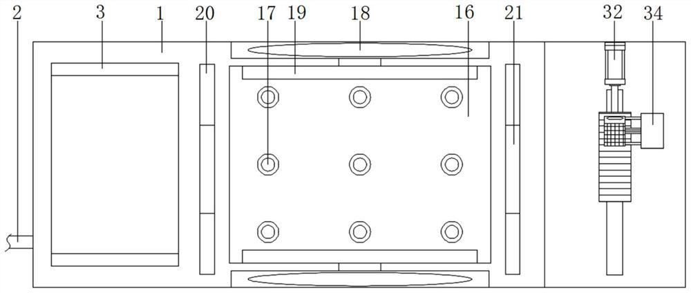
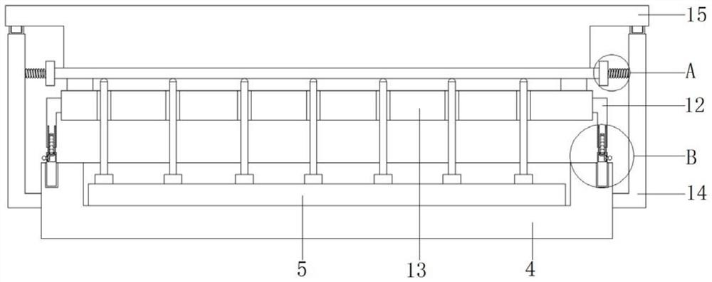
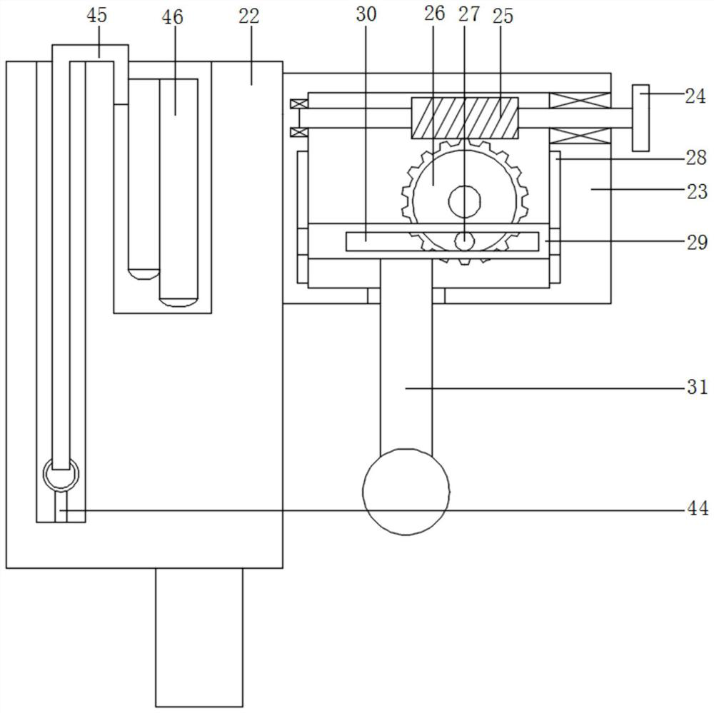
[0022] Example 1, see Figure 1 to Figure 6, the present invention provides a technical solution: a detection fixture for 3C product testing, including a base 1, a data transmission line 2 is fixedly connected to the left side of the base 1, and a notch is provided on the surface of the base 1 close to the left side thereof, The inner wall of the notch is fixedly connected with the adhesive plate 3, the surface of the adhesive plate 3 is abutted against the probe base plate-4, and the inner wall of the probe base plate-4 is fixedly installed with the probe group plate-5, and the probe base plate-4. The front side is provided with a clamping slot 6, and the inner wall of the clamping slot 6 is clamped with a clamping rod 7. Through the setting of the clamping rod 7 and the clamping groove 6, it is convenient for the staff to disassemble and assemble the lower splint 13 freely, and the inside of the clamping rod 7 is provided with a cavity , the inner wall of the cavity is conne...
Embodiment 2
[0028] Example 2, see Figure 1 to Figure 6 The difference between this embodiment and Embodiment 1 is that a short spring 41 is fixedly connected to the side of the L-shaped bar 14, and one end of the short spring 41 is fixedly connected to a side splint 42, which reduces the deviation of the placement position of the main board. The surface of the side clamp 42 and the surface of the L-shaped bar 14 are fixedly connected with a telescopic rod 43, and the telescopic rod 43 is located inside the short spring 41. By setting the short spring 41 and the telescopic rod 43, the side clamp 42 can be relatively stable. to move. The surface of the vertical plate 22 is provided with a placement groove, the rear side of the placement groove inner wall is fixedly connected with a collar bar 44, the surface of the collar bar 44 is fixedly equipped with an elastic band 45, and the end of the elastic band 45 away from the collar bar 44 is fixedly connected with a The touch screen cover 46,...
PUM
 Abstract
Description
Claims
Application Information
 - R&D Engineer
- R&D Manager
- IP Professional
- Industry Leading Data Capabilities
- Powerful AI technology
- Patent DNA Extraction
Browse by: Latest US Patents, China's latest patents, Technical Efficacy Thesaurus, Application Domain, Technology Topic, Popular Technical Reports.
© 2024 PatSnap. All rights reserved.Legal|Privacy policy|Modern Slavery Act Transparency Statement|Sitemap|About US| Contact US: help@patsnap.com


