RF coil assembly and MRI apparatus

A technology of coil components and coils, applied in the directions of instruments, applications, diagnostic recording/measurement, etc., can solve the problems of coil array positioning and fastening burden, complex coil arrays, etc., and achieve the effect of enhanced workflow, better positioning and fastening

Pending Publication Date: 2021-12-10
KONINKLJIJKE PHILIPS NV
View PDF3 Cites 0 Cited by
  • Summary
  • Abstract
  • Description
  • Claims
  • Application Information

AI Technical Summary

Problems solved by technology

However, it requires a contoured substrate and a polygonal patch array drawn on the contoured substrate surface to position the coil array on the substrate surface, which leads to complex coil array fabrication and also makes the coil array less precise on anatomical structures. Positioning and fastening becomes a burden

Method used


Image

  • RF coil assembly and MRI apparatus
  • RF coil assembly and MRI apparatus
  • RF coil assembly and MRI apparatus

Examples


Embodiment Construction

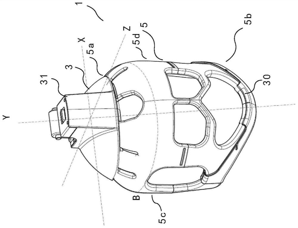
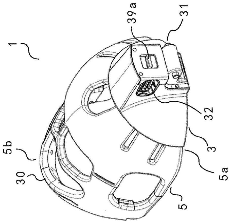
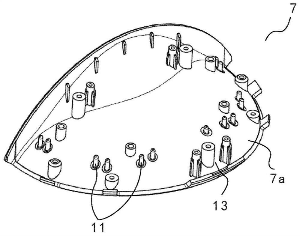
[0041] figure 1 is a perspective view showing an RF coil assembly according to a preferred embodiment of the present invention. figure 2 is like figure 1 Another perspective view of the RF coil assembly shown in . Such as figure 1 and figure 2 As shown in , the RF coil assembly 1 according to the present invention includes a first rigid frame 3 and a flexible coil 5 attached to the first rigid frame 3 . Figure 7 is a perspective view showing a flexible coil in a natural planar shape of an RF coil assembly. The flexible coil 5 has a first end 5a, a second end 5b opposite the first end 5a and two opposite sides 5c, 5d between the first end 5a and the second end 5b. The flexible coil 5 has a longitudinal axis L extending substantially from the first end 5a to the second end 5b and a transverse axis T perpendicular to the longitudinal axis L. As shown in FIG. The flexible coil 5 extends substantially in the plane defined by the longitudinal axis L and the transverse axis ...


PUM


Abstract

The present invention provides a RF coil assembly comprising a first rigid frame and a flexible coil in a naturally planar shape having a first end, a second end opposite the first end and a longitudinal axis extending from the first end to the second end. The first end of the flexible coil is attached to the first rigid frame and the second end of the flexible coil is away from the first rigid frame. The first rigid frame is shaped to bend the flexible coil, upon attaching the first end of the flexible coil to the first rigid frame, to form a shape of the RF coil assembly which conforms to a shape of a region of a subject with multiple contours. According to the present invention, the RF coil assembly is lighter and better matches the regions of different subjects to be imaged. The contoured shape of the RF coil assembly can be maintained for immediate use instead of having to achieve the shape by an operator attaching the flexible coil to body regions. Therefore, the positioning and fastening of the RF coil assembly is much easier and faster as compared to the conventional flexible coil, and the workflow of MR scanning is enhanced.

Description

technical field [0001] The present invention relates to an RF (Radio Frequency) coil assembly. More particularly, the present invention relates to an RF coil assembly suitable for use with magnetic resonance imaging (MRI) equipment. The invention also relates to an MRI apparatus comprising the RF coil assembly. Background technique [0002] RF coil assemblies are used in MRI equipment. In addition to "flat" coil assemblies, which are lightweight and useful for MRI scans of an area of ​​a subject, such as the abdomen, there are also "curved" coil assemblies that take a non-planar form. "Arc" coil assemblies typically have a hard plastic housing that surrounds the flexible coil to hold the coil assembly in its intended configuration. "Arcuate" coil assemblies may be used to perform MRI scans of areas of a subject, such as the head, shoulders, or ankles, where substantially flat coil assemblies would be inappropriate. Such "arc" coil assemblies are often cumbersome and rath...

Claims


Application Information

Patent Timeline
Patent Type & Authority Applications(China)
IPC IPC(8): G01R33/34
CPCG01R33/34007G01R33/34084A61B5/0042A61B5/055A61B5/702
Inventor 邓稳吴冰P·R·哈维
Owner KONINKLJIJKE PHILIPS NV
Why Eureka
Try Eureka