Electric logistics vehicle battery quick-changing device
A technology for quick battery replacement and logistics vehicles, applied in electric power units, power units, electric vehicles, etc., can solve the problems of troublesome, inconvenient, and inconvenient installation of battery replacement solutions, saving time and improving operational efficiency. Effect
- Summary
- Abstract
- Description
- Claims
- Application Information
AI Technical Summary
Problems solved by technology
Method used
Image

Examples
Embodiment 1
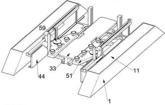
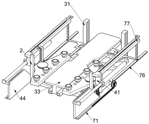
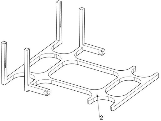
[0047] A battery quick-changing device for an electric logistics vehicle, such as figure 1 , figure 2 , image 3 , Figure 4 , Figure 5 , Image 6 , Figure 7 , Figure 8 , Figure 9 , Figure 10 , Figure 11 , Figure 12 , Figure 13 , Figure 13 , Figure 14 , Figure 15 , Figure 16 , Figure 17 , Figure 18 and 19 As shown, it includes a wheel frame 1, a special-shaped support base plate 2, a lifting assembly 3, a push assembly 4, a bolt removal assembly 5, a bolt installation assembly 6, and a push-pull assembly 7. The two wheel frames 1 are fixed on the ground, and the special-shaped support base plate 2 The lifting assembly 3 is arranged symmetrically on the top, the pushing assembly 4 is arranged symmetrically on the special-shaped support base plate 2, and the bolt removal assembly 5 is symmetrically slidingly connected to the special-shaped support base plate 2, and the bolt removal assembly 5 is used to remove the bolts from the new energy vehicle...
Embodiment 2
[0058] On the basis of Example 1, such as Figure 15 , Figure 16 and Figure 17 As shown, a reset assembly 8 is also included. A reset assembly 8 for resetting is provided on one side of the rectangular slide rail frame 77. The reset assembly 8 includes a second return spring 81, a rectangular slotted frame 82, a wedge-shaped card frame 83, and a second return spring 81. A return spring 84 and a second return spring 85, a second return spring 81 is connected between the special-shaped rack frame 76 and the rectangular slide rail frame 77, and the second return spring 81 is used to drive the special-shaped rack frame 76 and its upper The device moves and resets in a direction away from the special-shaped support frame 41. A rectangular slotted frame 82 is fixedly installed on one side of the rectangular slide rail frame 77. The rectangular slotted frame 82 is used to clamp the special-shaped rack frame 76, and the wedge-shaped card frame 83 is slidingly connected. On the rec...
Embodiment 3
[0061] On the basis of Example 2, such as Figure 18 As shown, it also includes arc angle 10, and the wedge-shaped push frame 44 is evenly arranged to open the limit groove 9, the limit groove 9 is used to limit the special-shaped sliding frame 63 and the upper device, the limit groove 9 Arc angles 10 are arranged on both sides, and the arc angles 10 are convenient to push the special-shaped sliding frame 63 to move above the wedge-shaped pushing frame 44 .
[0062] Through the effect of the limit groove 9 and the arc angle 10, when the special-shaped sliding frame 63 and its upper device are pushed to move above the wedge-shaped push frame 44, the special-shaped sliding frame 63 and its upper device can be limited to avoid the special-shaped sliding frame. 63 and its upper device position shifted.
PUM
 Abstract
Description
Claims
Application Information
 - R&D
- Intellectual Property
- Life Sciences
- Materials
- Tech Scout
- Unparalleled Data Quality
- Higher Quality Content
- 60% Fewer Hallucinations
Browse by: Latest US Patents, China's latest patents, Technical Efficacy Thesaurus, Application Domain, Technology Topic, Popular Technical Reports.
© 2025 PatSnap. All rights reserved.Legal|Privacy policy|Modern Slavery Act Transparency Statement|Sitemap|About US| Contact US: help@patsnap.com