
Material distributing device and conveying equipment

A material distributing device and feeding device technology, which is applied in the field of conveying machinery, can solve the problems of material stacking, tumbling, and poor material distribution, and achieve the effect of preventing material stacking and uniform material distribution

Pending Publication Date: 2021-12-14
SHENHUA WUHAI COAL GROUP CORP +1
View PDF0 Cites 0 Cited by
  • Summary
  • Abstract
  • Description
  • Claims
  • Application Information

AI Technical Summary

Problems solved by technology

[0003] In the prior art, the material distributing device adopts the form of a single-segment receiving plate or a multi-segment receiving plate connected at a slant. If the angle between the receiving plate and the horizontal plane is too large, it may cause the round part of the material to roll over, resulting in overlapping Other materials, resulting in poor cloth effect; if the angle between the receiving plate and the horizontal plane is too small, it may cause the flat part of the material to stop moving on the receiving plate, resulting in stacking
There are irregularities in the shape of the material, so it is not easy to find a suitable setting angle of the receiving plate in actual production

Method used


Image

  • Material distributing device and conveying equipment
  • Material distributing device and conveying equipment
  • Material distributing device and conveying equipment

Examples


Embodiment Construction

[0030] Embodiments of the present invention will be further described below in conjunction with the accompanying drawings. In the description of the present invention, it should be noted that the terms "center", "upper", "lower", "left", "right", "vertical", "horizontal", "inner", "outer" etc. The indicated orientation or positional relationship is based on the orientation or positional relationship shown in the drawings, and is only for the convenience of describing the simplified description of the present invention, rather than indicating or implying that the device or component referred to must have a specific orientation or a specific orientation. construction and operation, therefore, should not be construed as limiting the invention. In addition, the terms "first", "second", and "third" are used for descriptive purposes only, and should not be construed as indicating or implying relative importance. Wherein, the terms "first position" and "second position" are two diff...


PUM


Abstract

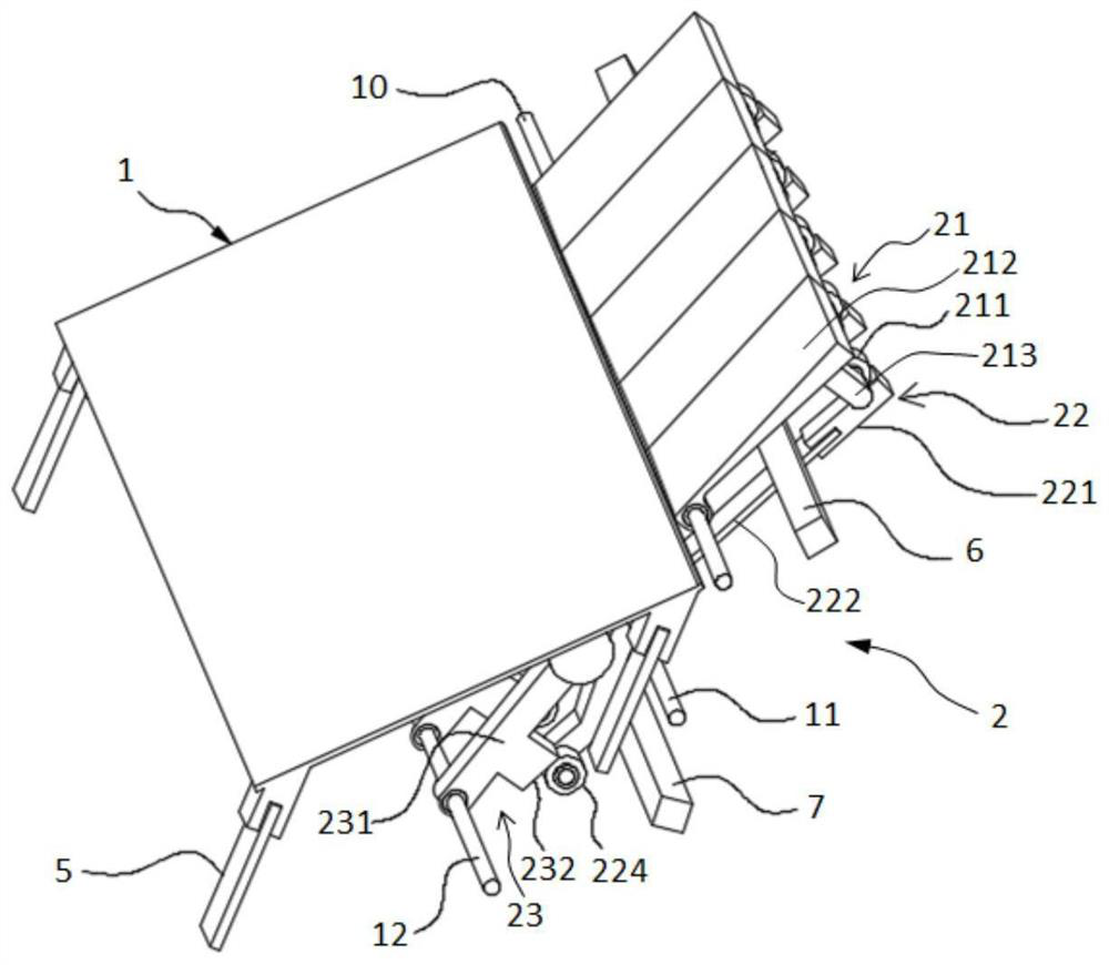
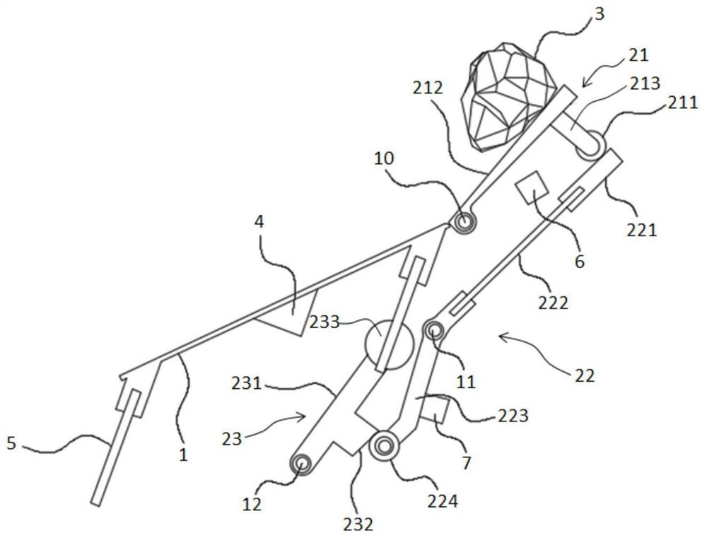
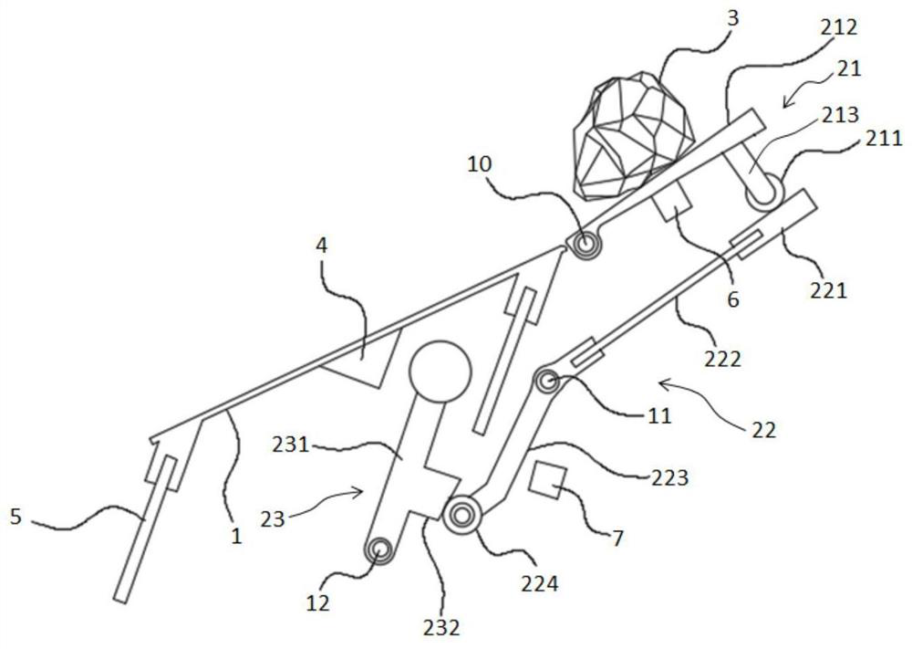
The invention provides a material distributing device and conveying equipment. The material distributing device comprises a supporting frame, a sliding plate connected with the supporting frame, and a plurality of beating units sequentially arranged in the width direction of the sliding plate. Each beating unit comprises a touch plate, a transmission assembly and a beating assembly, wherein the touch plate is rotatably connected with the supporting frame and used for guiding materials in falling onto the sliding plate, the transmission assembly is rotatably connected with the supporting frame, the first end of the transmission assembly is located on the moving path of the touch plate, the beating assembly is rotatably connected with the supporting frame, located on the moving path of the second end of the transmission assembly and pushed by the second end of the transmission assembly to rotate, and the sliding plate is located on the moving path of the beating assembly. By the adoption of the material distributing device, the inclination angle of the sliding plate is small, and the materials cannot roll over; the sliding plate is forced to vibrate when beaten by the beating units, then the materials smoothly slide along the sliding plate, and the included angle between the sliding plate and the horizontal plane does not need to be excessively considered; and meanwhile, the material distributing device can adapt to materials in various shapes and guarantee a uniform material distributing effect to prevent material stacking.

Description

technical field [0001] The invention relates to the technical field of conveying machinery, in particular to a material distribution device and conveying equipment. Background technique [0002] When arranging materials in the dry separator, a distributing device is usually installed between the upstream feeding device and the downstream feeding device. The material will accelerate during the falling process of the feeding device, increasing the distance between the materials falling at different times. The distributing device Undertake the falling material, and stably transport it to the downstream conveying device, and then use the height difference between the upstream feeding device and the downstream conveying device to increase the distance between the materials, so as to achieve the effect of uniform distribution. [0003] In the prior art, the material distributing device adopts the form of a single-segment receiving plate or a multi-segment receiving plate connected...

Claims


Application Information

Patent Timeline
IPC IPC(8): B65G11/02B65G11/20
CPCB65G11/026B65G11/206
Inventor 韩春阳陶健蔚志恒李伟涛郝俊飞冀磊高燕军张清彬徐新娟梁超臣
Owner SHENHUA WUHAI COAL GROUP CORP
Learn More