Sponge road with rainwater permeation function

A function and sponge technology, applied in the field of road construction, can solve problems such as increasing safety hazards, affecting road use, and poor road water seepage performance, and achieve the effects of strengthening the overall structural strength, increasing drainage speed, and preventing blockage

Pending Publication Date: 2021-12-14
CHINA THIRD METALLURGICAL GRP
0 Cites 0 Cited by

AI-Extracted Technical Summary

Problems solved by technology

The combination of rainwater harvesting system technology and green space construction will greatly change our life, which is depleted due to the depletion of water resources. The sidewalks on the roads in cities are very common, and everyone is accustomed to them. Most of the existing sidewalks are with The cement sidewalk or asphalt sidewalk o...

Method used

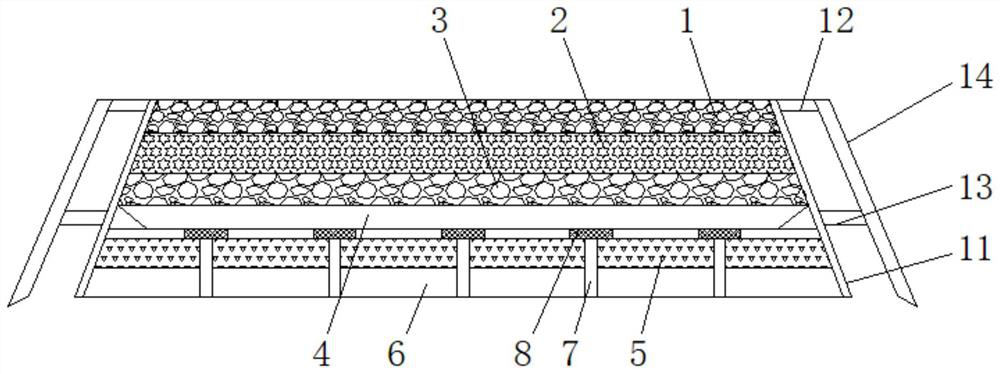
Please refer to Fig. 1-3, a kind of sponge road that possesses rainwater infiltration function, comprises permeable floor layer 1, and the outside of permeable floor layer 1 and permeable road base 2 are all fitted with reinforcing guard plate 11, strengthen The bottom of the inner side of the guard plate 11 is closely attached to the outer side of the foundation stone layer 6 and the water seepage layer 5, and the top of the outer side of the reinforced guard plate 11 is fixedly installed with a connecting plate 12, and the outer end of the connecting plate 12 is fixedly installed with a plug-in plate 14. A reinforcing plate 13 is fixedly installed between the inner side of the plate 14 and the reinforcing guard plate 11. The plug-in plate 14 is arranged parallel to the reinforcing guard plate 11. 1. Water-permeable holes are provided at the joints of the permeable road base 2 and the permeable sand layer 3. By adding reinforcement guards 11 on the side of the road construction materials, the overall structural strength of the road can be strengthened, and the plug-in plate 14 further strengthens the road. The reinforced guard plate 11 is supported and reinforced, and the overall structure of the sponge road has been strengthened on the original basis, and it is not easy to collapse. By adding a filter screen 8 on the top of the drainage tank 7, the dirt can be blocked to prevent damage to the drainage tank. 7 cause blockage, the bottom of the permeable floor layer 1 is laid with a permeable road base 2, the bottom of the permeable road base 2 is laid with a permeable sand layer 3, and the bottom of the permeable sand layer 3 is fitted with a support seat 4, and the support seat 4 A raised block 15 is fixedly installed on the top of the raised block 15, and the upper end of the raised block 15 is clamped to the inside of the water seepage sandstone layer 3, and the inside of the support seat 4 is provided with a water filter hole 16, and the water filter hole 16 is connected to the inside of the support seat 4. The holes are used together, the two ends of the support seat 4 are arranged in an inclined ...

Abstract

The invention discloses a sponge road with rainwater permeation function. The sponge road with the rainwater permeation function comprises a permeable terrace layer, a permeable waterway base layer is laid at the bottom of the permeable terrace layer, a water seepage gravel layer is laid at the bottom of the permeable waterway base layer, a supporting seat is arranged at the bottom of the water seepage gravel layer in an attached mode, through holes are formed in the supporting seat, and are communicated with the interior of the water seepage gravel layer. Drainage grooves are additionally formed in the road, rainwater can be drained to the underground, water collecting grooves in the water seepage layer are used for collecting the infiltrated rainwater in a centralized mode, water guiding grooves can drain the rainwater into the drainage grooves in a centralized mode, the rainwater is further drained to the bottom of base stone layer, accumulated water on the surface of the road can be treated in time, meanwhile, the water seepage layer can drain part of rainwater and is used in cooperation with the water guiding groove, the water drainage speed is increased, materials adopted by the road have the water seepage function, and accumulated water can be rapidly drained.

Application Domain

Sewerage structuresPaving gutters/kerbs

Technology Topic

StormwaterWater seepage +3

Image

  • Sponge road with rainwater permeation function
  • Sponge road with rainwater permeation function
  • Sponge road with rainwater permeation function

Examples

  • Experimental program(1)

Example Embodiment

[0020] The technical solutions in the embodiments of the present invention will be clearly and completely described below with reference to the accompanying drawings in the embodiments of the present invention. Obviously, the described embodiments are only a part of the embodiments of the present invention, but not all of the embodiments. Based on the embodiments of the present invention, all other embodiments obtained by those of ordinary skill in the art without creative efforts shall fall within the protection scope of the present invention.
[0021] In the description of this application document, it should be understood that the terms "center", "upper", "lower", "front", "rear", "left", "right", "vertical", "horizontal" , "top", "bottom", "inside", "outside" and other indicated orientations or positional relationships are based on the orientations or positional relationships shown in the accompanying drawings, and are only for the convenience of describing this patent and simplifying the description, rather than indicating or It is implied that the device or element referred to must have a particular orientation, be constructed and operate in a particular orientation, and therefore should not be construed as a limitation of this patent. In the description of this application document, it should be noted that, unless otherwise expressly specified and limited, the terms "installed", "connected", "connected" and "arranged" should be understood in a broad sense, for example, it may be a fixed connection, The setting can also be a detachable connection and setting, or an integral connection and setting. For those of ordinary skill in the art, the specific meanings of the above terms in this patent can be understood according to specific situations.
[0022] see Figure 1-3 , a sponge road with rainwater infiltration function, including a permeable floor layer 1, the outer sides of the permeable floor layer 1 and the permeable road base layer 2 are fitted with a reinforcing guard plate 11, and the bottom of the inner side of the reinforcing guard plate 11 and the cornerstone layer. 6 and the outer side of the permeable layer 5 are closely attached, the top of the outer side of the reinforcing guard plate 11 is fixedly installed with a connecting plate 12, the outer end of the connecting plate 12 is fixedly installed with a plug-in board 14, and the inner side of the plug-in board 14 is fixed with the reinforcing guard plate 11. A reinforcing plate 13 is fixedly installed therebetween, the plug-in plate 14 is arranged in parallel with the reinforcing guard plate 11, the plug-in plate 14 is arranged in an inclined shape on the outer side of the reinforcing guard plate 11, the permeable floor layer 1, the permeable road base layer 2 and the permeable sand The joints of the stone layers 3 are provided with permeable holes. By adding a reinforcing guard plate 11 on the side of the road building material, the overall structural strength of the road can be strengthened. The overall structure of the sponge road has been strengthened on the original basis, and it is not easy to slump. By adding a filter screen 8 on the top of the drainage groove 7, the dirt can be blocked to prevent the drainage groove 7 from being blocked. The permeable floor layer 1 The bottom of the water-permeable road base 2 is laid with a water-permeable gravel layer 3, and the bottom of the water-permeable gravel layer 3 is fitted with a support base 4, and the top of the support base 4 is fixedly installed with a raised block 15. , the upper end of the raised block 15 is clamped to the inside of the water-permeable sandstone layer 3, and the inside of the support seat 4 is provided with a water filter hole 16, and the water filter hole 16 is used in conjunction with the through hole inside the support seat 4. The end is arranged in an inclined shape, and a cushion block is arranged at the inclined part. The bottom of the cushion block is provided with a stone layer. The filter screen 8 is clamped inside the stone layer. The interior of the layer 3 is connected, the bottom of the support base 4 is laid with a water permeable layer 5, the water permeable layer 5 and the cornerstone layer 6 are both provided with a drainage structure, and the two are connected to each other, and the bottom of the water permeable layer 5 is laid with a cornerstone layer 6, The inside of the water permeable layer 5 is provided with a drainage groove 7, the top of the drainage groove 7 is at the same level as the top of the water permeable layer 5, a filter screen 8 is clamped at the water inlet position on the top of the drainage groove 7, and the lower end of the drainage groove 7 extends to the cornerstone layer. Inside 6, the top of the water permeable layer 5 is provided with a water collecting groove 9, and the bottom of the water collecting groove 9 is connected with a water guiding groove 10. The lower end of the aqueduct 10 is communicated with the drainage trough 7. By adding the drainage trough 7 inside the road, the rainwater can be drained to the ground, and the infiltrated rainwater can be collected by the sump 9 inside the permeable layer 5. , and the gutter 10 can concentrate the rainwater to the inside of the gutter 7, and further to the bottom of the cornerstone layer 6, so that the surface water of the road can be treated in time, and the water seepage layer 5 can discharge part of the rainwater, and cooperate with The water guide troughs 10 are used together to improve the drainage speed, and all the materials used in the road have the function of water seepage, which can quickly discharge the accumulated water.
[0023] When in use, rainwater can penetrate into the ground from the surface of the permeable material on the top of the road, and enter the interior of the water collection tank 9 after infiltrating through the support seat 4, and part of the rainwater is discharged to the ground through the drainage groove 7, and the water collection tank inside the water seepage layer 5. 9. After the infiltrated rainwater is collected, the rainwater is drained to the inside of the drainage groove 7 by using the water guide 10, and further to the bottom of the cornerstone layer 6, so that the surface water of the road can be treated in time, and the water seepage layer 5 Part of the rainwater can be discharged and used together with the water guide 10 to improve the drainage speed, and the materials used in the road all have the function of water seepage, which can quickly discharge the accumulated water.
[0024] Although embodiments of the present invention have been shown and described, it will be understood by those skilled in the art that various changes, modifications, and substitutions can be made in these embodiments without departing from the principle and spirit of the invention and modifications, the scope of the present invention is defined by the appended claims and their equivalents.

PUM

no PUM

Description & Claims & Application Information

We can also present the details of the Description, Claims and Application information to help users get a comprehensive understanding of the technical details of the patent, such as background art, summary of invention, brief description of drawings, description of embodiments, and other original content. On the other hand, users can also determine the specific scope of protection of the technology through the list of claims; as well as understand the changes in the life cycle of the technology with the presentation of the patent timeline. Login to view more.

Similar technology patents

Electric heating stove

PendingCN107606681Aprevent heat lossspeed up drainage
Owner:TIANJIN SANMUSEN ELECTRIC FURNACE

Steam-water separating box drainage system of sealing oil vacuum pump

PendingCN106799103Aimprove securityspeed up drainage
Owner:DATANG HANCHENG NO 2 POWER GENERATION

Waterproof construction method for convex skylight of steel structure roof

InactiveCN112609907AGood waterproof effectspeed up drainage
Owner:HEBEI TIANXIN CONSTR GRP CO LTD

Magnetic type rapid drainage floor drain

PendingCN113482133Aspeed up drainageGood deodorant effect
Owner:YUHUAN YU GOVERNANCE PLUMBING CO LTD

Water immersion control circuit for medical instrument

PendingCN113050707Aspeed up drainageeasy to view
Owner:尹业兴

Classification and recommendation of technical efficacy words

  • speed up drainage
  • Improve overall structural strength

Spongy urban siphoning and water-draining roof

InactiveCN106437042Aincrease pressure differencespeed up drainage
Owner:绍兴职业技术学院

Stink-leaking prevention device and floor drain with stink-leaking prevention device thereof

PendingCN110042911Aspeed up drainage
Owner:台州信各灵卫浴科技有限公司

Efficient heat exchange tube for condensation

PendingCN108801033Aspeed up drainageIncrease the heat exchange area
Owner:上海欧贡制冷科技有限公司 +1

Electric heating stove

PendingCN107606681Aprevent heat lossspeed up drainage
Owner:TIANJIN SANMUSEN ELECTRIC FURNACE

Waterproof construction method for convex skylight of steel structure roof

InactiveCN112609907AGood waterproof effectspeed up drainage
Owner:HEBEI TIANXIN CONSTR GRP CO LTD

Guide shell structure of dehumidifier

InactiveCN102109213AImprove deformation resistanceImprove overall structural strength
Owner:LG ELECTRONICS (TIANJIN) APPLIANCES CO LTD

Improved structure of wiring terminal

InactiveCN102842785AImprove overall structural strengthImprove shrapnel holding force
Owner:DINKLE ENTERPRISE

Seabed in-situ integrated neutron activation analysis system

PendingCN107462589AImprove overall structural strengthincrease the reaction cross section
Owner:CHENGDU UNIVERSITY OF TECHNOLOGY

Fan impeller

InactiveCN101377208AImprove overall structural strengthreduce overall weight
Owner:SUNONWEALTH ELECTRIC MACHINE IND

Preparation method of fiber mesh-compounded diatom ooze coating

InactiveCN112266631AImprove overall structural strengthImprove flexibility
Owner:佘丽辉
Why Eureka
Try Eureka