Photoacoustic gas sensor device

A sensor device, photoacoustic gas technology, applied in the direction of measuring devices, instruments, scientific instruments, etc., can solve the problems of long optical path length, complexity, large size of photoacoustic gas sensor, etc., to achieve stable construction and not easy to mechanical instability Effect

Pending Publication Date: 2021-12-14
SENSIRION AG
View PDF0 Cites 0 Cited by
  • Summary
  • Abstract
  • Description
  • Claims
  • Application Information

AI Technical Summary

Problems solved by technology

[0005] Conventional photoacoustic gas sensors are large in size due to the long optical path lengths required for adequate absorption of infrared radiation by the molecules of the constituents
Furthermore, conventional photoacoustic gas sensors require complex three-dimensional assemblies of measurement cells, infrared sources, and pressure transducers

Method used


Image

  • Photoacoustic gas sensor device
  • Photoacoustic gas sensor device
  • Photoacoustic gas sensor device

Examples


Embodiment Construction

[0034] The same elements are denoted by the same reference numerals in all figures.

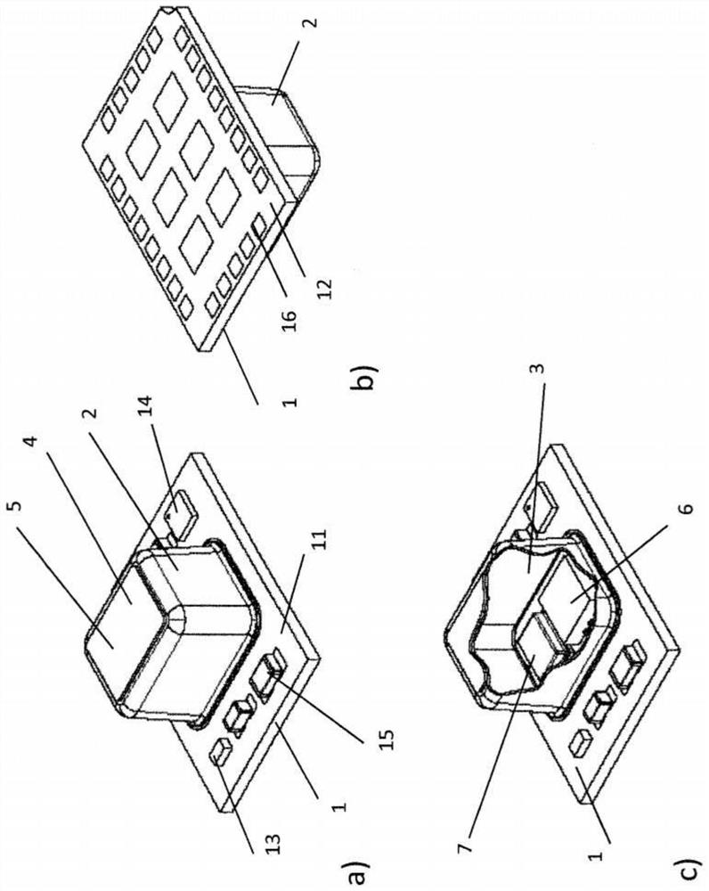
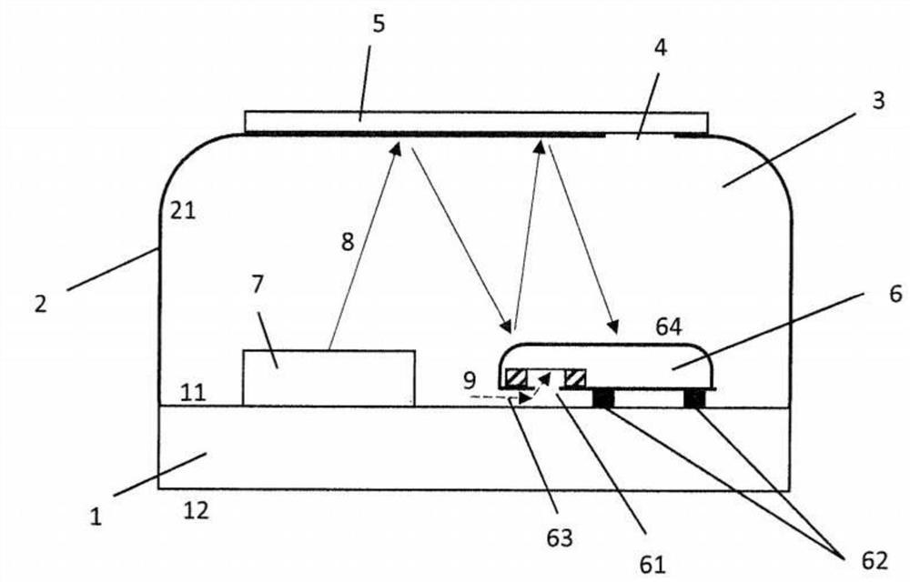
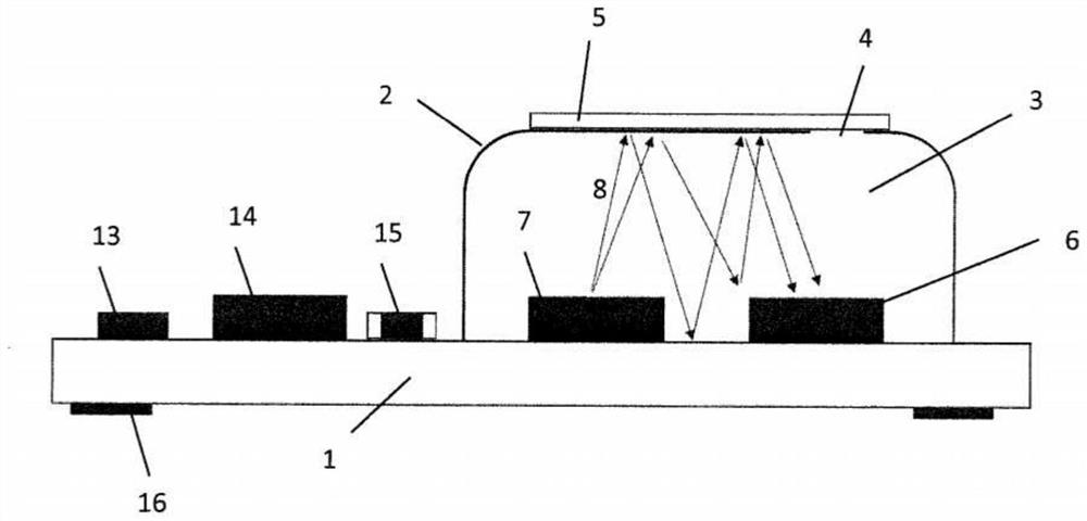
[0035] figure 1 A perspective view of a photoacoustic gas sensor device according to an embodiment of the invention is shown from above and from below. The device comprises a substrate 1 , eg a printed circuit board (PCB), and a measuring cell body 2 , which together form a measuring cell surrounding a measuring volume 3 . The measuring cell has holes 4 to allow gas exchange between the measuring volume 3 and the surroundings of the device. exist figure 1 In, the hole 4 is located in the main body 2 of the measuring cell. The pores 4 are preferably covered by a membrane 5 which is gas permeable to allow gas exchange such that the concentration of the component of interest in the gas is similar to that in the environment.

[0036] The substrate 1 has a first side 11 and a second side 12 . On the first side 11 the measuring cell body 2 is arranged, as well as the other parts described belo...


PUM

PropertyMeasurementUnit
sizeaaaaaaaaaa
widthaaaaaaaaaa
reflectanceaaaaaaaaaa

Abstract

A photoacoustic gas sensor device is proposed for determining a value indicative of a presence or a concentration of a component in a gas. The photoacoustic gas sensor device comprises a substrate (1), and a measurement cell body (2) arranged on a first side (11) of the substrate (1). The substrate (1) and the measurement cell body (2) define a measurement cell enclosing a measurement volume (3). The measurement cell comprises an aperture (4) for a gas to enter the measurement volume (3). The device further comprises an electromagnetic radiation source (7) for emitting electromagnetic radiation (8), and a microphone (6) for measuring a sound wave (9) generated by the component in response to an absorption of electromagnetic radiation (8) by the component. The electromagnetic radiation source (7) and the microphone (6) are arranged on the first side (11) of the substrate (1) and in the measurement volume (3). The microphone (6) has a bottom port (61) facing the substrate (1), and the measurement volume (3) is communicatively coupled to the bottom port (61).

Description

[0001] Cross References to Related Applications [0002] This application claims priority from European Patent Application 19169966.9 filed on April 17, 2019, the disclosure of which is hereby incorporated by reference in its entirety. technical field [0003] The invention relates to a photoacoustic gas sensor device configured to determine components in an indicating gas, in particular CO 2 The value of the presence or concentration. Background technique [0004] Photoacoustic gas sensors rely on physical effects such as infrared radiation being absorbed by gases such as CO 2 Molecular absorption of the component of interest, thereby transferring the molecule to an excited state. The subsequent heat generation due to the non-radiative decay of the excited state, for example through collisions of molecules, leads to an increase in pressure. By modulating the infrared radiation to be absorbed at the modulation frequency, the pressure is varied at the modulation frequency....

Claims


Application Information

Patent Timeline
Patent Type & Authority Applications(China)
IPC IPC(8): G01N21/17
CPCG01N21/1702G01N2021/1704G01N2021/1706G01N2021/1708G01N29/2418G01N21/3504
Inventor T·优林格
Owner SENSIRION AG
Why Eureka
Try Eureka