Discharge lamp comprising a discharge vessel and an electrode frame

A discharge vessel and electrode holder technology, which is applied in the field of discharge lamps, can solve the problems of high cost and troublesome manufacturing, and achieve the effect of easy handling and cost advantages

Inactive Publication Date: 2009-09-16
OSRAM GMBH
View PDF1 Cites 0 Cited by
  • Summary
  • Abstract
  • Description
  • Claims
  • Application Information

AI Technical Summary

Problems solved by technology

[0004] The constructions known from the prior art are relatively complex to produce and are therefore also expensive

Method used


Image

  • Discharge lamp comprising a discharge vessel and an electrode frame

Examples


Embodiment Construction

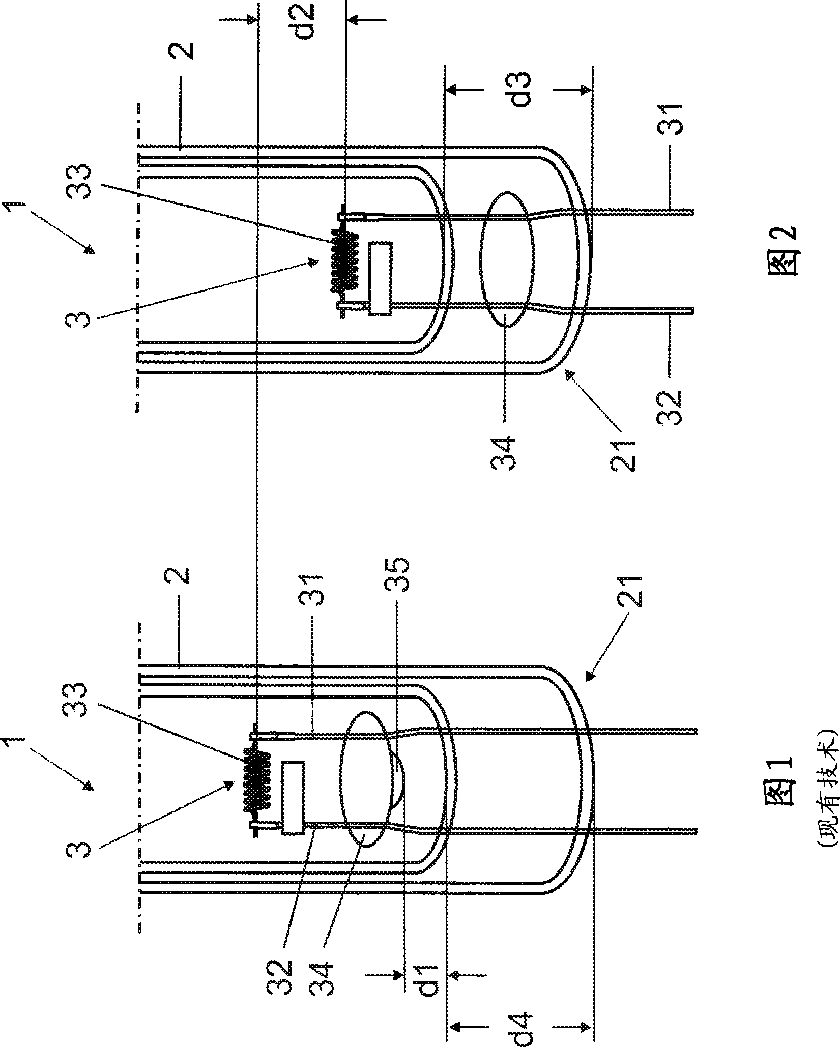
[0021] In the figures, identical or functionally identical elements are provided with the same reference signs.

[0022] The discharge lamp 1 embodied as a low-pressure discharge lamp comprises a tubular discharge vessel 2 having a lower end region 21 which is extruded. The electrode holder 3 protrudes partially into the discharge vessel 2 and comprises two wire-shaped electrode holders 31 and 32 . A filament 33 is arranged as an electrode on the front ends of the two electrode holders 31 and 32 which are arranged in the discharge vessel 2 . The glass bead 34 extends between the two electrode holders 31 and 32 and is pressed completely into the end region 21 in the exemplary embodiment. The glass material of the end region 21 differs from the glass material of the glass beads 34 in this exemplary embodiment. In particular, the two glass materials are constructed such that their coefficients of thermal expansion differ from one another, so that when a temperature gradient occ...


PUM


Abstract

The invention relates to a discharge lamp comprising a discharge vessel (2) and an electrode frame (3) which is provided with a lamp coil (33) and at least some sections of which extend into the discharge vessel (2). Electrode holders (31, 32) are connected to a glass bead (34), at least some areas of which are sealed into an end region (21) of the discharge vessel (2).

Description

technical field [0001] The invention relates to a discharge lamp with a discharge vessel and an electrode carrier, wherein the electrode carrier has a filament, wherein the electrode carrier protrudes at least partially into the discharge vessel and the electrode holder is connected to a glass bead. Background technique [0002] DE 10 2004 004 655 A1 discloses a low-pressure discharge lamp in which the electrode carrier projects into the discharge space through an end region of the discharge vessel. The electrode holders of the electrode holder are fused gas-tight at the end regions of the discharge vessel, and glass beads located in the discharge vessel are arranged between the electrode holders. [0003] Furthermore, FIG. 1 shows a similarly constructed low-pressure discharge lamp 1 having a discharge vessel 2 into which an electrode carrier 3 projects partially. In the end region 21 in which the discharge vessel 2 is squeezed, the electrode holders 31 and 32 of the elect...

Claims


Application Information

Patent Timeline
Patent Type & Authority Applications(China)
IPC IPC(8): H01J61/36
CPCH01J61/366
Inventor 托马斯·诺尔阿尔弗雷德·兰格克劳斯·潘克拉茨格拉尔德·黑默
Owner OSRAM GMBH
Why Eureka
Try Eureka