Step-by-step feeding mechanism applied to continuous ejection clip applier

A technology of feeding mechanism and clamping forceps, applied in the field of medical devices, can solve the problem that the handle cannot be fired effectively, and achieve the effect of reducing the amplitude and preventing mis-clamping

Active Publication Date: 2021-12-17
HANGZHOU KANGJI MEDICAL INSTR
View PDF14 Cites 1 Cited by
  • Summary
  • Abstract
  • Description
  • Claims
  • Application Information

AI Technical Summary

Problems solved by technology

[0004] This utility model patent has the advantage of solving the problem that the handle cannot be effectively fire

Method used


Image

  • Step-by-step feeding mechanism applied to continuous ejection clip applier
  • Step-by-step feeding mechanism applied to continuous ejection clip applier
  • Step-by-step feeding mechanism applied to continuous ejection clip applier

Examples


Embodiment Construction

[0025] The present invention will be described in further detail below in conjunction with the accompanying drawings and specific embodiments.

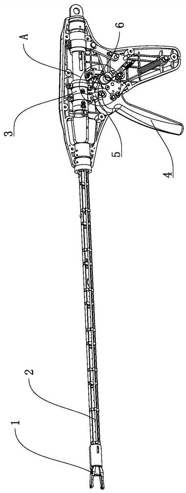
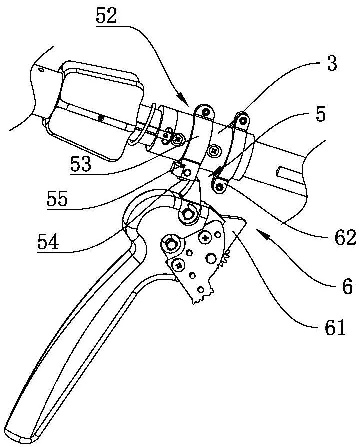
[0026] combine figure 1 and figure 2 As shown, a step-by-step feed mechanism applied to continuous clamping pliers, including a pincer head 1 and a pincer head push rod 2 connected to the pincer head 1, moving the pincer head push rod 2 can drive the pincer head 1 is opened or clamped, the pincer head push rod 2 and the pincer head 1 can be connected by the common connection method of the clamp applicator in the prior art, so as to realize the opening and closing action of the control pincer head 1. The end of the pliers head push rod 2 away from the pliers head 1 is connected with a propulsion structure 3, and a first feed mechanism 5 and a second feed mechanism 6 are also provided between the drive handle 4 and the propulsion structure 3. The drive handle 4 The first feeding mechanism 5 pushes the propelling structure 3 into the ...


PUM


Abstract

The invention belongs to the technical field of medical instruments, and particularly relates to a step-by-step feeding mechanism applied to a continuous ejection clip applier. The invention provides the step-by-step feeding mechanism applied to the continuous ejection clip applier, and aims to solve the problem that in the prior art, when a tissue clip is ejected out of a clip applier, a large-amplitude automatic bounce-off action occurs, and the inconvenience is brought to medical staffs in the surgical operation process. The step-by-step feeding mechanism comprises a clamp head and a clamp head push rod with one end connected to the clamp head; the end, away from the clamp head, of the clamp head push rod is connected with a propelling structure; a first feeding mechanism and a second feeding mechanism are further arranged between a driving handle and the propelling structure; the driving handle pushes the propelling structure into a first feeding space through the first feeding mechanism; and the driving handle pushes the propelling structure into a second feeding space through the second feeding mechanism. According to the invention, the amplitude of the automatic bounce-off action of the tissue clip can be reduced, and then the tissue clip is slowly clamped to be completely closed by using the second feeding mechanism, so that the step-by-step feeding mechanism is more suitable for the tissue clip which can be automatically bounced off during ejection.

Description

technical field [0001] The invention belongs to the technical field of medical devices, and in particular relates to a step-by-step feeding mechanism applied to continuous clip applicators. Background technique [0002] A clip applier is a surgical instrument used to clamp tissue clips during surgery. Usually, the tissue clips can be made of metal materials, such as titanium clips, or other materials, such as plastic clips. When the tissue clip is being clamped, it is necessary to push the tissue clip out of the clip applier first, and then use the pliers head to close the tissue clip to achieve clamping. However, some tissue clips, such as plastic tissue clips, will have a large automatic springing action when they are pushed out to the position of the clamp applicator, which brings inconvenience to the medical staff during the operation. [0003] For example, a Chinese utility model patent discloses a clamp applicator [application number: 202022036634.6]. The body is mo...

Claims


Application Information

Patent Timeline
IPC IPC(8): A61B17/128
CPCA61B17/1285
Inventor 唐文鹏周鹏贺丁丁程磊
Owner HANGZHOU KANGJI MEDICAL INSTR
Why Eureka
Try Eureka