
Probe-type electrical testing machine

An electrical measuring machine and probe-type technology, applied in the field of electrical measuring machines, can solve the problems of low detection efficiency, high detection cost, cumbersome and other problems, and achieve the effects of improving detection efficiency, improving stability and simple operation.

Pending Publication Date: 2021-12-17
深圳市合力泰光电有限公司
View PDF0 Cites 0 Cited by
  • Summary
  • Abstract
  • Description
  • Claims
  • Application Information

AI Technical Summary

Problems solved by technology

[0003]Some needle-type electric measuring machines on the existing market are often only a single testing device. During the testing process, manual feeding, unloading or When used together with other equipment, the detection cost is high; for the detection structure, manual marking is required, the process is cumbersome, the detection efficiency is not high, and human errors are prone to occur. These existing problems still need to be further resolved

Method used


Image

  • Probe-type electrical testing machine
  • Probe-type electrical testing machine
  • Probe-type electrical testing machine

Examples


Embodiment 1

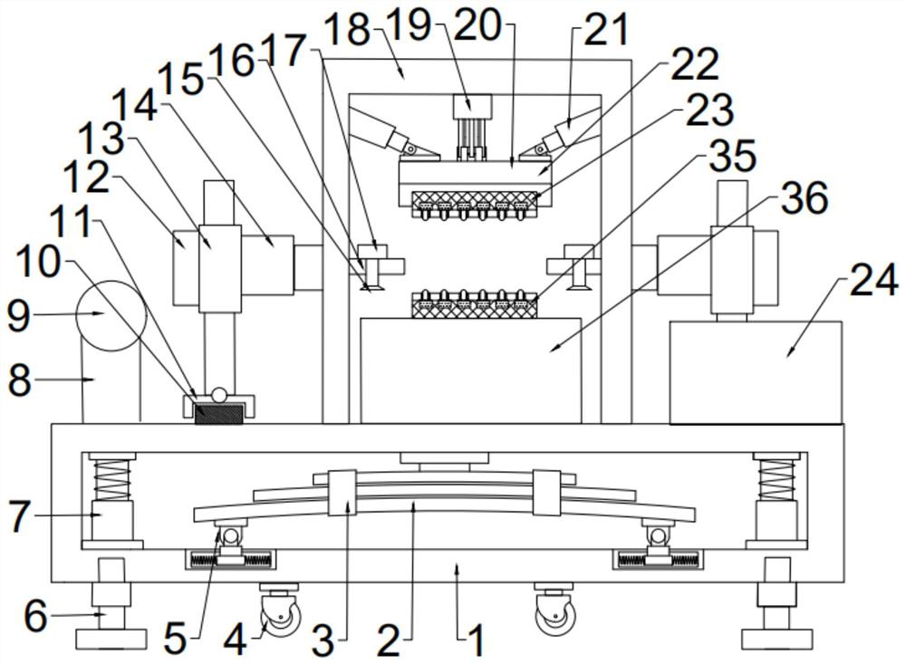
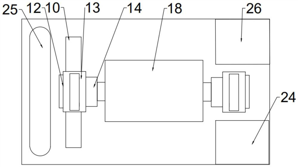
[0030] see Figure 1~5 , in an embodiment of the present invention, a probe-type electric measuring machine includes a base 1, and a product transportation device, a material retrieving device, a detection device, a feeding device and a product storage box are installed on the top of the base 1; wherein, the detection device A reclaiming device and an unloading device are respectively installed on both sides, the product transport device is located on the left side of the unloading device, and the product storage box is located on the right side of the unloading device.

[0031] The top side of the base 1 is symmetrically installed with a rotating shaft 9, and the bottom end of the rotating shaft 9 is equipped with a supporting column 8, and the end of the supporting column 8 away from the rotating shaft 9 is fixedly installed on the upper surface of the base 1, and the outer surface of the rotating shaft 9 is installed. Conveyor belt 25; the top of the base 1 is equipped with...

Embodiment 2

[0033] see Figure 1-5 , the difference between this embodiment and embodiment 1 is:

[0034] In this embodiment, a sliding structure is installed on the bottom of the base 1, and the sliding structure includes two symmetrically structured wheels 4 and fixed feet 6. The outer top of the wheel 4 is fixedly connected to the connecting plate through bolts, and the connecting plate is far away from the wheel 4. One side of the base 1 is rotatably connected with the rotating shaft, and the rotating shaft is installed on the bottom of the base 1 through the fixed block, and two fixed feet 6 of the same structure are respectively installed on both sides of the bottom of the base 1 away from the fixed block, and the fixed feet 6 are provided with There are threads, and the support height of the fixed feet 6 can be adjusted by screwing, so as to determine whether the wheels 4 are in contact with the ground, so that the entire probe-type electric measuring machine equipment can be moved...


PUM


Abstract

The invention relates to the technical field of electrical testing machines, in particular to a probe-type electrical testing machine. The probe-type electrical testing machine comprises a base, rotating shafts are symmetrically installed on one side of the top of the base, supporting columns are installed at the bottom ends of the rotating shafts, the ends, away from the rotating shafts, of the supporting columns are fixedly installed on the upper surface of the base, a material taking device is installed on the side, close to a product conveying belt, of the top of the base, a product detection table is installed on the side, close to the material taking device, of the top of the base, a lower detection device is installed on the top of the product detection table, a fixing support is installed on the outer side of the product detection table and provided with a lifting device, an upper detection device is installed on the lower side of the lifting device, a fixing plate is installed on the side, away from the material taking device, of the product detection table, the bottom end of the fixing plate is installed on the upper surface of the base, a discharging device is installed on the fixing plate, and the material taking device and the discharging device are the same in structure. The whole device can realize automatic material taking and detection and classify detected products, and is simple to operate and convenient to transport.

Description

technical field [0001] The invention relates to the technical field of electric measuring machines, in particular to a probe type electric measuring machine. Background technique [0002] Probes are the contact medium for electrical testing. They are high-end precision electronic hardware components. In the testing of electronic product circuits, probe-type electrical testing machines are often used to check whether they are qualified. [0003] Some needle-type electrical measuring machines on the existing market are often only a single testing device. During the testing process, it is necessary to manually take and unload materials or use them together with other equipment, and the testing cost is relatively high; for the testing structure , needs to be marked manually, the process is cumbersome, the detection efficiency is not high and human errors are prone to occur, these existing problems still need to be further solved. Contents of the invention [0004] The purpose...

Claims


Application Information

Patent Timeline
IPC IPC(8): B07C5/344B07C5/02
CPCB07C5/344B07C5/02
Inventor 马承义
Owner 深圳市合力泰光电有限公司
Learn More