
Redundant-degree-of-freedom mechanical arm path planning method and device and engineering machinery
A technology of path planning and manipulators, applied in manipulators, program-controlled manipulators, manufacturing tools, etc., can solve problems such as the inability to reduce the vibration at the end of the manipulator arm execution, and achieve the effect of reducing jitter and reducing the number of joints
Patent Information
- Authority / Receiving Office
- CN · China
- Patent Type
- Applications(China)
- Current Assignee / Owner
- Publication Date
- 2021-12-17
Smart Images
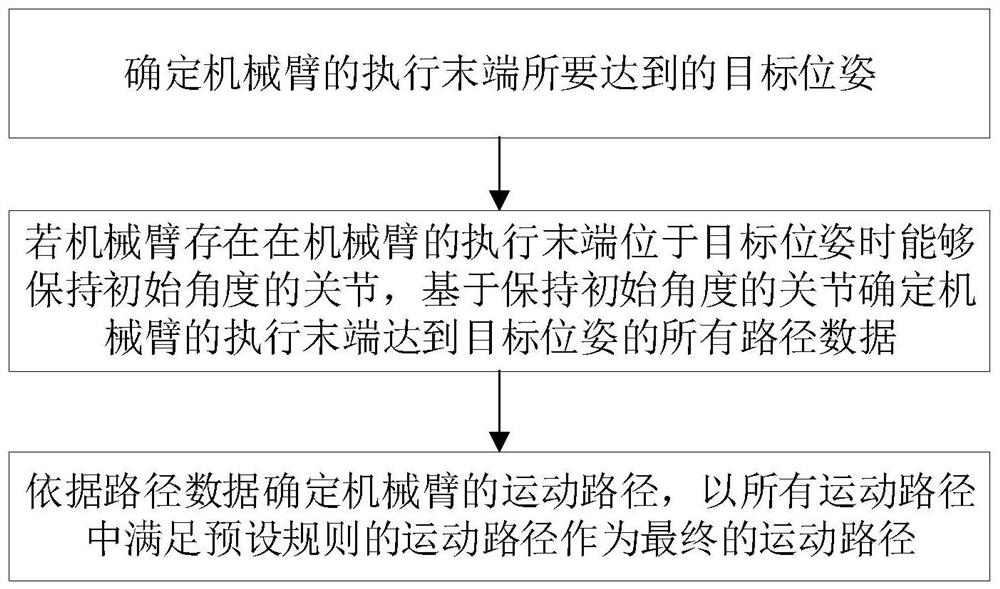
Figure 1 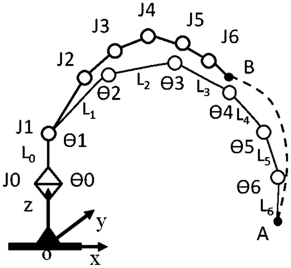
Figure 2 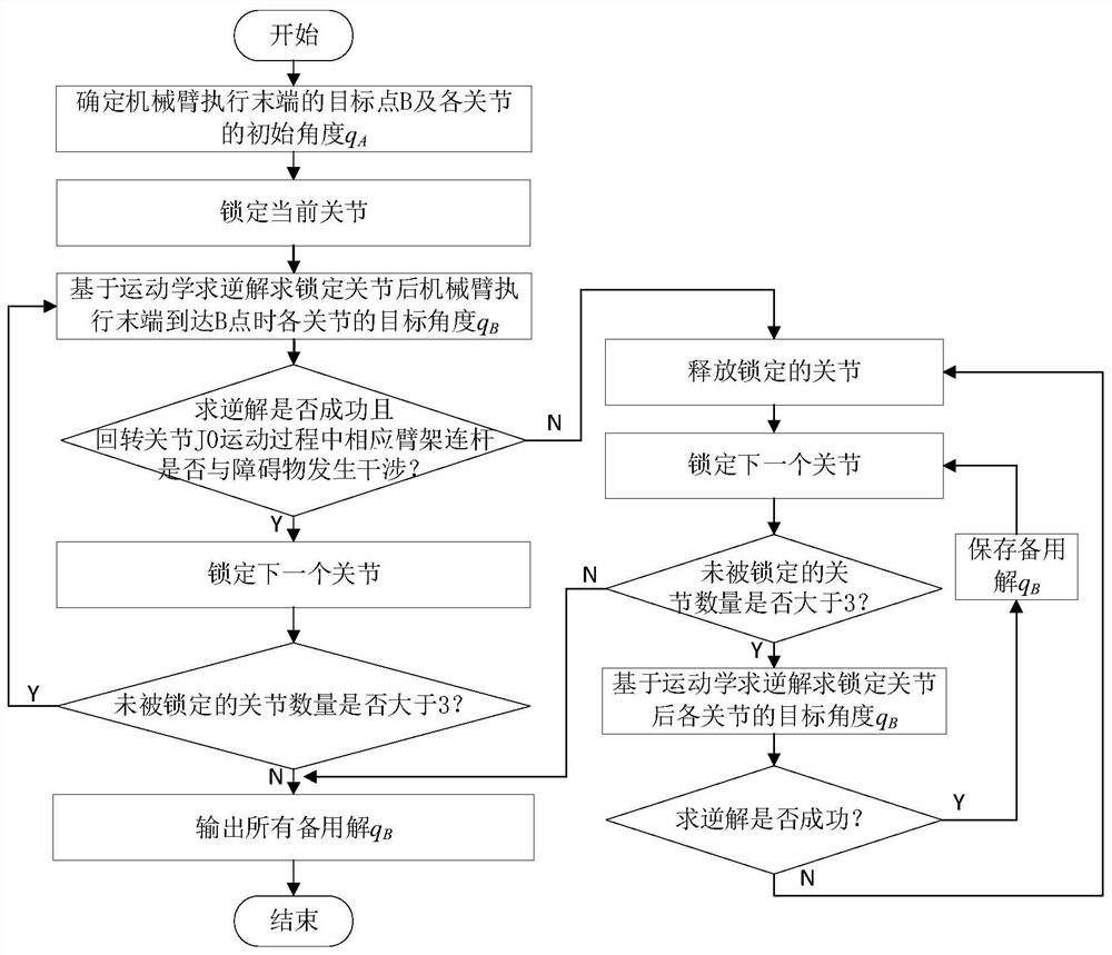
Figure 3
Abstract
Description
technical field
[0001] The invention relates to the technical field of path planning of a mechanical arm, in particular to a path planning method for a redundant degree of freedom mechanical arm, a path planning device for a redundant degree of freedom mechanical arm, and an engineering machine. Background technique
[0002] Existing construction machinery jibs usually have a relatively large size, and often have a large inertia when the mechanical arm performs an action, and because the driving device of the existing construction machinery jib is often hydraulically driven, and the output power of the hydraulic pump Limited, so the linkage of multiple joints of the mechanical arm frame causes greater vibration at the execution end of the mechanical arm. During the movement of the mechanical arm, the more moving joints, the greater the vibration at the execution end of the mechanical arm, especially the closer to the mechanical arm. The movement of the joints of the boom bas...
Examples
Embodiment Construction
[0048] Specific embodiments of the present invention will be described in detail below in conjunction with the accompanying drawings. It should be understood that the specific embodiments described here are only used to illustrate and explain the present invention, and are not intended to limit the present invention.
[0049] Such as figure 1 As shown, in the first aspect of this embodiment, a path planning method for a redundant degree of freedom robotic arm is provided, including:
[0050]Determine the target pose to be achieved by the execution end of the manipulator; determine the joints that can maintain the initial angle when the execution end of the manipulator is at the target pose among all the joints of the manipulator; determine the execution end of the manipulator based on the determined joints To achieve the path data of the target pose, the path data includes the target angles of all joints of the manipulator, and the target angle of at least one joint is equal ...