Sound barrier vibration attenuation and energy consumption device of distributed additional damping structure

A technology of additional damping and energy-consuming devices, applied in the direction of noise absorption devices, bridge parts, bridges, etc., can solve the problems of aggravating the superstructure of the bridge, loss, and weakening the sound insulation performance of the sound barrier, so as to reduce the vibration of the sound barrier and avoid bolts. The effect of falling off and increasing the vibration damping function

Pending Publication Date: 2021-12-17
WUHAN UNIV OF TECH
View PDF6 Cites 0 Cited by
  • Summary
  • Abstract
  • Description
  • Claims
  • Application Information

AI Technical Summary

Problems solved by technology

These engineering problems not only weaken or even lose the sound insulation performance of the sound barrier, but also cause potential safety hazards for trains.
[0003] In reality, the auxiliary facilities on elevated rail transit bridges, especially the sound barrier structure, have been affected by vehicle-induced vibration for a long time. The existing vibration reduction measures focus on the vibration reduction of the track structure, and the vibration reduction / vibration reduction measures of the bridge structure such as basin rubber support Seats, rubber damping bearings, etc. will aggravate the vibration of the bridge superstructure. It is difficult for existing bearing structures to meet the requirements of vertical and horizontal bearing capacity at the same time.

Method used


Image

  • Sound barrier vibration attenuation and energy consumption device of distributed additional damping structure
  • Sound barrier vibration attenuation and energy consumption device of distributed additional damping structure
  • Sound barrier vibration attenuation and energy consumption device of distributed additional damping structure

Examples


Embodiment Construction

[0026] In order to make the object, technical solution and advantages of the present invention clearer, the present invention will be further described in detail below in conjunction with the accompanying drawings and embodiments. It should be understood that the specific embodiments described here are only used to explain the present invention, not to limit the present invention.

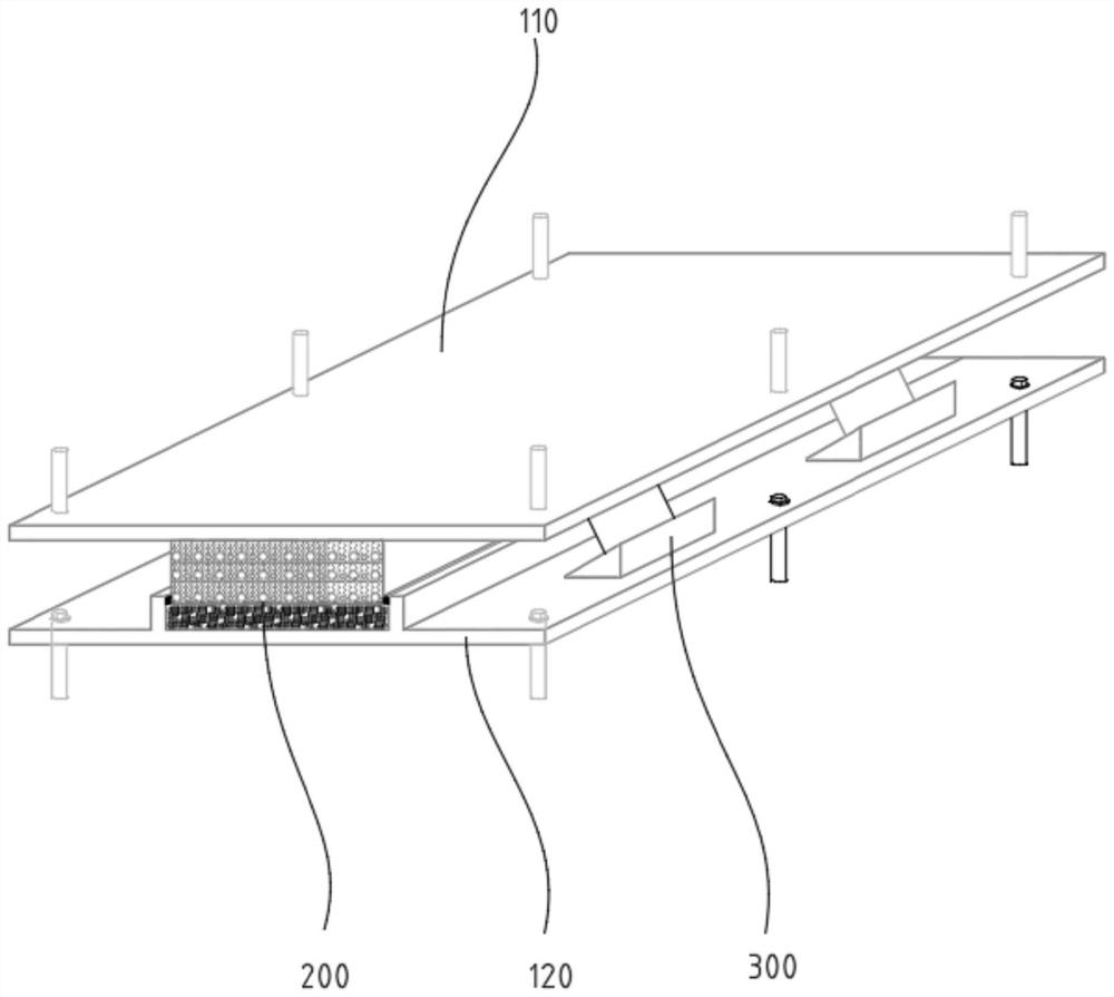
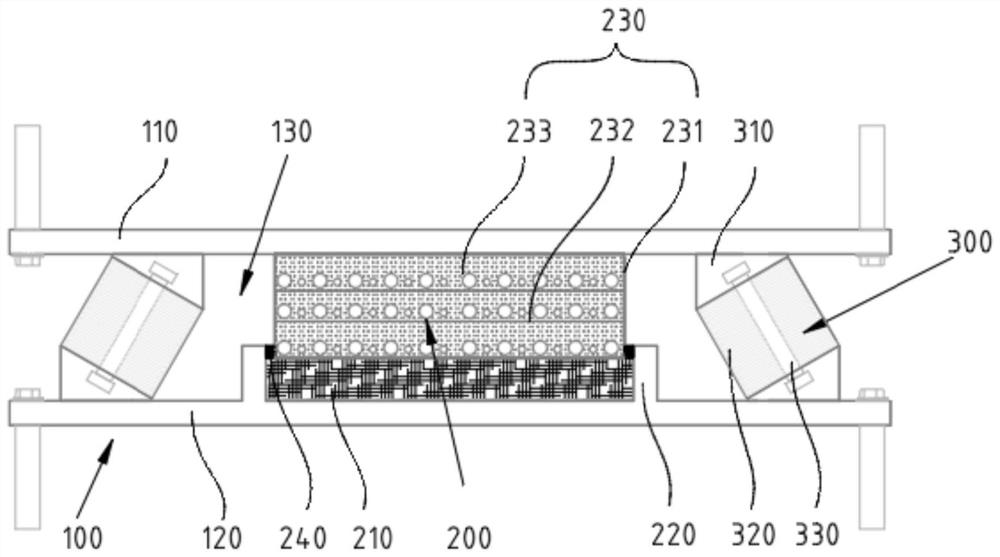
[0027] see Figure 1-3 As shown, the present invention provides a sound barrier vibration reduction and energy dissipation device with a distributed additional damping structure, including a support mechanism 100, a first vibration reduction mechanism 200 and a second vibration reduction mechanism 300, wherein the support mechanism 100 includes upper An installation area 130 is formed between the supporting plate 110 and the lower supporting plate 120 , and between the upper supporting plate 110 and the lower supporting plate 120 . The first damping mechanism 200 is fixedly installed in the instal...


PUM


Abstract

The invention discloses a sound barrier vibration attenuation and energy consumption device of a distributed additional damping structure, comprising: a support mechanism comprising an upper support plate and a lower support plate which are arranged at an interval, wherein an installation area being formed between the upper support plate and the lower support plate; a first vibration reduction mechanism which is fixedly installed in the installation area, wherein the first vibration reduction mechanism comprises an elastic cushion, a limiting ring and a vibration reduction damper, the top of the vibration reduction damper is fixedly connected with the upper support plate, and the bottom of the vibration reduction damper abuts against the elastic cushion; and a second vibration reduction mechanism, wherein the second vibration reduction mechanism and the first vibration reduction mechanism are arranged in a spaced mode and fixedly installed in the installation area. The vibration attenuation and energy consumption device provides enough bearing force to bear the sound barrier, the vibration of the sound barrier on the upper portion of a bridge can be effectively reduced, and the phenomena that bolts fall off, acrylic plates crack, aluminum alloy pressing strips are snapped and the like of the sound barrier are avoided.

Description

technical field [0001] The invention relates to the technical field of civil engineering, in particular to a sound barrier vibration reduction and energy consumption device with a distributed additional damping structure. Background technique [0002] In 2003, the sound barrier on the Cologne-Frankfurt high-speed railway in Germany was damaged due to the impact of the pulsating force of the train. The main reason is that the natural frequency of the sound barrier is close to the frequency of the interference force, which causes the dynamic response of the structure to increase. Under the influence of the dynamic load, the force and the column produce different degrees of bending deformation, which causes the panel to twist, and the unit panels are connected by rivets. The part is damaged. Recently, in the domestic rail transit, not only the high-speed railway but also the urban rail transit operating at a lower speed (≤100km / h), the sound barriers on the viaducts have simil...

Claims


Application Information

Patent Timeline
Patent Type & Authority Applications(China)
IPC IPC(8): E01F8/00E01D19/10
CPCE01F8/00E01D19/103E01F8/0047
Inventor 孙亮明樊金龙朱文进
Owner WUHAN UNIV OF TECH
Why Eureka
Try Eureka