Combined holding device for electric vehicles

A technology for retaining devices and electric vehicles, applied to shafts and bearings, bearing cooling, bearing components, etc., can solve problems such as general cage heat dissipation performance, cage burns, fractures, etc., to reduce temperature, avoid excessive wear, and avoid bias moving effect

Active Publication Date: 2022-03-29
杭州优协科技有限公司
View PDF10 Cites 0 Cited by
  • Summary
  • Abstract
  • Description
  • Claims
  • Application Information

AI Technical Summary

Problems solved by technology

However, the heat dissipation performance of this combined cage is average, and it is easy to cause burns and fractures of the cage at high temperatures

Method used


Image

  • Combined holding device for electric vehicles
  • Combined holding device for electric vehicles
  • Combined holding device for electric vehicles

Examples


Embodiment 1

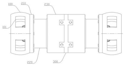
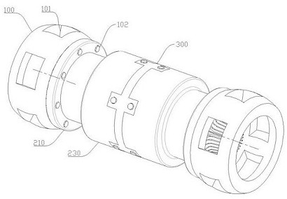
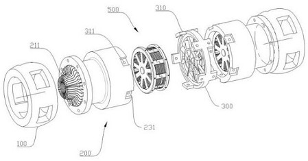
[0037] Such as figure 1 , 2 As shown in , 3, the combined holding device for electric vehicles includes two oppositely placed cages 100, steel ball grooves 101 are evenly arranged around the cages 100, mounting holes 102 are arranged around the opposite sides of the cage 100, and the cage 100 A mounting hole 102 is opened, and a first connector 200 is connected to the opposite side of the cage 100. The first connector 200 includes a first base body 210. The first base body 210 is an annular structure. Corresponding to the hole body, the opposite side of the first base body 210 is fixedly connected to the first ring body 220, the first ring body 220 is coaxially arranged with the first base body 210, and the opposite side of the first ring body 220 is fixedly connected to the tubular first ring sleeve 230, the first Engaging grooves 231 are formed around opposite side edges of the collar 230 .

[0038] In the present invention, through the design of the first base body 210 an...


PUM


Abstract

The invention discloses a combined retaining device for an electric vehicle, which relates to the field of new energy automobile parts, and comprises two relatively placed retainers, steel ball grooves are evenly arranged around the retainer, mounting holes are arranged around opposite sides of the retainer, and the retainer A mounting hole is opened, and a first connecting piece is connected to the opposite side of the cage. The first connecting piece includes a first base body. The first base body is a ring structure. The base body is coaxially arranged, the opposite side of the first ring body is fixedly connected to the tubular first ring sleeve, and the opposite side edge of the first ring sleeve is surrounded by a snap-in groove; the opposite side of the first ring sleeve is provided with a ring-shaped second base body. The two bases are respectively connected to the first connectors on both sides, and both sides of the second base are provided with snap-in blocks corresponding to the snap-in slots on the first ring; the snap-in slots and the snap-in blocks are correspondingly provided with fastening hole. Solving the problem of not being able to dissipate heat efficiently, the combined type keeps the device running smoothly for a long time and is easy to disassemble.

Description

technical field [0001] The invention belongs to the field of new energy automobile parts, and in particular relates to a combined holding device for electric automobiles. Background technique [0002] The descriptions in this section merely provide background information related to the disclosure in this application and may not constitute prior art. [0003] The cage, that is, the bearing cage, refers to the bearing part that partially wraps all or part of the rolling body and moves with it, to isolate the rolling body, and usually guide the rolling body and keep it in the bearing. When the rolling bearing is working, Especially when the load is complex and rotates at high speed, the cage has to bear a lot of centrifugal force, shock and vibration, there is a large sliding friction between the cage and the rolling elements, and a lot of heat is generated, the result of the combined force and heat will be It will cause the cage to fail, and in severe cases, it will cause the...

Claims


Application Information

Patent Timeline
Patent Type & Authority Patents(China)
IPC IPC(8): F16C33/40F16C37/00
CPCF16C33/40F16C37/007F16C2326/01
Inventor 周晶
Owner 杭州优协科技有限公司
Why Eureka
Try Eureka