High-sensitivity anti-interference photoacoustic imaging system

A photoacoustic imaging and sensitive technology, applied in medical science, diagnosis, diagnostic recording/measurement, etc., can solve problems such as vibration and affecting the sensitivity of photoacoustic imaging system devices, so as to avoid equipment damage, improve sensitivity, and reduce vibration amplitude Effect

Pending Publication Date: 2022-02-11
SHANDONG UNIV
View PDF0 Cites 0 Cited by
  • Summary
  • Abstract
  • Description
  • Claims
  • Application Information

AI Technical Summary

Problems solved by technology

[0002] The photoacoustic imaging system is often used as a means of detecting patients in medical treatment. The light source emitted by the transmitter is used to irradiate the designated area of ​​​​the patient to check the disease. The light source transmitter in the existing photoacoustic imaging system is usually used in conjunction with the photoacoustic imaging system. The main body is fixedly connected. This connection method has certain disadvantages. The photoacoustic imaging system itself is a precision instrument, and there are many small parts inside the light source transmitter. However, the photoacoustic imaging system needs to be close to the patient when examining the patient. Even direct contact will cause a certain vibration when accidentally touching or hitting the body of the photoacoustic imaging system, and frequent purchases will affect the sensitivity of the entire device of the photoacoustic imaging system to a certain extent

Method used


Image

  • High-sensitivity anti-interference photoacoustic imaging system
  • High-sensitivity anti-interference photoacoustic imaging system
  • High-sensitivity anti-interference photoacoustic imaging system

Examples


Embodiment Construction

[0030] The following will clearly and completely describe the technical solutions in the embodiments of the present invention with reference to the accompanying drawings in the embodiments of the present invention. Obviously, the described embodiments are only some, not all, embodiments of the present invention. Based on the embodiments of the present invention, all other embodiments obtained by persons of ordinary skill in the art without making creative efforts belong to the protection scope of the present invention.

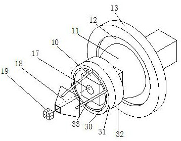
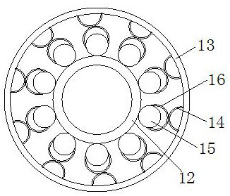
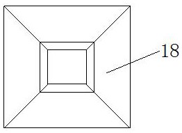
[0031] see Figure 1-6, a highly sensitive and anti-jamming photoacoustic imaging system, comprising a light source transmitter body 10, the light source transmitter body 10 is movably connected to the photoacoustic imaging system body through a first-order buffer mechanism, and the first-order buffer mechanism includes a sphere-11, a circular plate- 12. Disc two 13, arc one 14, sphere two 15, arc two 16 and baffle one 17, the light source emitter body 10 runs...


PUM


Abstract

The invention relates to the technical field of photoacoustic imaging equipment, and discloses a high-sensitivity anti-interference photoacoustic imaging system which comprises a light source emitter body; the light source emitter body is movably connected with a photoacoustic imaging system body through a first-order buffer mechanism, and the light source emitter body shifts to drive a first sphere to push a first circular plate. A first circular plate pushes a second sphere to slide on a corresponding second arc piece so that an opening of the corresponding second arc piece can be enlarged, the second sphere slides into the second arc piece, so that the second arc piece deforms to absorb part of vibration generated by the light source emitter body, and the second sphere slides in the second arc piece. The force of the second sphere to the second arc piece is transmitted to the corresponding first arc piece through the second arc piece, so that the corresponding first arc piece is deformed, vibration generated by the light source emitter body is further absorbed, the amplitude of vibration generated by the light source emitter body when the photoacoustic imaging system body is impacted by the outside is reduced, and the service life of the light source emitter body is prolonged; and the sensitivity of the light source emitter body is improved.

Description

technical field [0001] The invention relates to the technical field of photoacoustic imaging equipment, in particular to a highly sensitive anti-interference photoacoustic imaging system. Background technique [0002] The photoacoustic imaging system is often used as a means of detecting patients in medical treatment. The light source emitted by the transmitter is used to irradiate the designated area of ​​​​the patient to check the disease. The light source transmitter in the existing photoacoustic imaging system is usually used in conjunction with the photoacoustic imaging system. The main body is fixedly connected. This connection method has certain disadvantages. The photoacoustic imaging system itself is a precision instrument, and there are many small parts inside the light source transmitter. However, the photoacoustic imaging system needs to be close to the patient when examining the patient. Even direct contact will cause a certain vibration when accidentally touchi...

Claims


Application Information

Patent Timeline
Patent Type & Authority Applications(China)
IPC IPC(8): A61B5/00
CPCA61B5/0095
Inventor 王春王剑磊孟宪凤冯天利
Owner SHANDONG UNIV
Why Eureka
Try Eureka