Method and system for exporting waste heat of reactor core in containment

A technology for waste heat removal system and core waste heat, applied in the field of nuclear industry, can solve the problems of high construction and operation and maintenance costs, and cannot meet the requirements of mutual independence, so as to reduce construction and operation and maintenance costs, simplify safety facilities, and improve safety. sexual effect

Pending Publication Date: 2021-12-17
CHINA NUCLEAR POWER ENG CO LTD
View PDF1 Cites 0 Cited by
  • Summary
  • Abstract
  • Description
  • Claims
  • Application Information

AI Technical Summary

Problems solved by technology

[0004] For this design, under the design basis accident conditions, two special safety systems, the safety injection system and the containment sprinkler system, and the waste heat removal system are required to cooperate with each other to take out the waste heat of the core,

Method used


Image

  • Method and system for exporting waste heat of reactor core in containment
  • Method and system for exporting waste heat of reactor core in containment

Examples


Embodiment 1

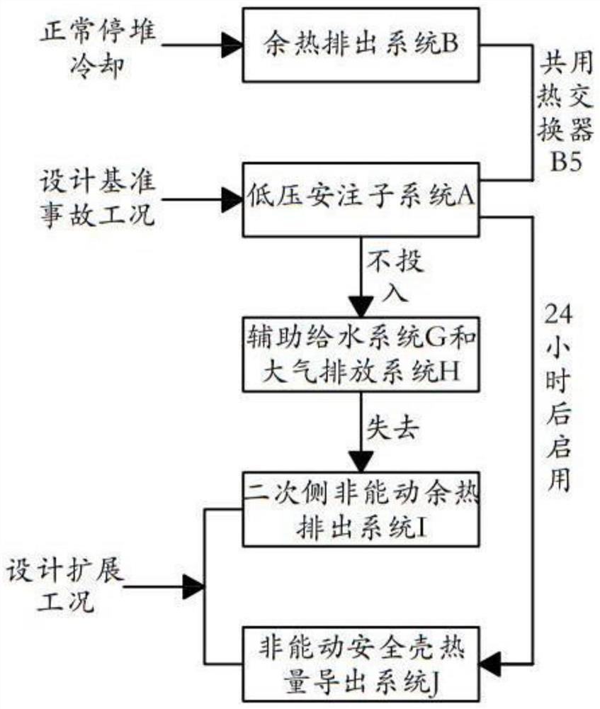
[0061] Such as figure 1 with 2 As shown, Embodiment 1 of the present invention provides a method for deriving residual heat from the core in the containment, the method comprising:

[0062] Under the design basis accident conditions, the low-pressure safety injection subsystem A of the safety injection system is connected with the heat exchanger B6 of the waste heat removal system B. When the primary circuit reaches the injection pressure of the low-pressure safety injection system A, the low-pressure safety injection subsystem A Inject the built-in refueling water tank / pit E boron-containing water (that is, coolant F1) into the core K2, and the coolant F1 that has absorbed the waste heat of the core K2 flows out from the breach of the primary circuit and returns to the built-in refueling water tank / pit E, and then exported from the low-pressure safety injection subsystem A to the heat exchanger B6 for heat exchange and cooling, and the coolant F1 after the heat exchange and ...

Embodiment 2

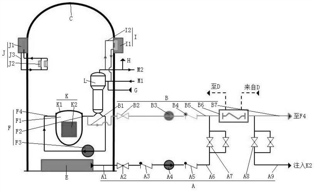
[0068] Such as figure 2 As shown, Embodiment 2 of the present invention provides a core residual heat export system in the containment vessel, including:

[0069] Containment C, whose volume meets the design basis accident conditions, and when the low-pressure safety injection subsystem A is put into use, the pressure inside it shall not exceed its design pressure value for at least 24 hours. This design requirement will be combined with the low-pressure safety injection Subsystem A introduces its specific working principle and function.

[0070] Specifically, a reactor K is arranged in the containment C, and the reactor K includes a reactor pressure vessel K1 and a core K2 arranged in the reactor pressure vessel K1, and the reactor pressure vessel K1 is filled with coolant F1. In a specific embodiment, Coolant F1 can use boron-containing cooling water (also known as boric acid water, boron-containing water, which is one of the commonly used coolants in nuclear reactors), an...


PUM


Abstract

The invention discloses a method and system for exporting waste heat of a reactor core in a containment. The method comprises the steps that a low-pressure safety injection subsystem of a safety injection system is communicated with a heat exchanger of a waste heat removal system under a design basis accident working condition, wherein the low-pressure safety injection subsystem exports a coolant absorbing the waste heat of the reactor core to the heat exchanger for heat exchange and cooling, the coolant subjected to heat exchange and cooling by the heat exchanger returns and is injected into the reactor core, the coolant circularly flows, and the waste heat of the reactor core is continuously exported until the reactor core is in a safe state; under the design basis accident working condition and the condition that the low-pressure safety injection subsystem is put into use, the volume of the containment does not exceed the design pressure of the containment within at least 24 hours, and the combined design can simplify specially-arranged safety facilities, ensure the independence of the second level and the third level of depth defense, improve the safety and reduce the construction, operation and maintenance cost.

Description

technical field [0001] The invention belongs to the technical field of the nuclear industry, and in particular relates to a method and system for deriving residual heat from a reactor core in a containment vessel. Background technique [0002] As one of the important facilities for nuclear power plant reactor core protection, the containment vessel needs to be equipped with a good heat export system to quickly and effectively export the residual heat of the core and the heat in the containment vessel under accident conditions. [0003] Refer to the patent application document with the patent publication number CN104217773A, a general nuclear power plant is equipped with a containment spray system, a safety injection system, and a waste heat removal system for deriving containment and core waste heat under design basis accident conditions: containment spray The system is used to export the heat of the containment under the design basis accident conditions, and transfer the he...

Claims


Application Information

Patent Timeline
IPC IPC(8): G21C15/18
CPCG21C15/18G21C15/182Y02E30/30
Inventor 黄伟峰堵树宏毛亚蔚张利孙占杨长江
Owner CHINA NUCLEAR POWER ENG CO LTD
Why Eureka
Try Eureka