
Thermodynamic diagram generation method based on base station coverage area, electronic equipment and medium

A coverage area and heat map technology, applied in location-based services, electrical components, wireless communications, etc., can solve problems such as low accuracy, inability to accurately obtain pseudo-base station coverage, inability to accurately obtain the number of base station equipment, etc.

Active Publication Date: 2021-12-17
杭州云深科技有限公司
View PDF11 Cites 2 Cited by
  • Summary
  • Abstract
  • Description
  • Claims
  • Application Information

AI Technical Summary

Problems solved by technology

[0002] In the prior art, operators use triangulation to determine the coverage of base stations, which has low accuracy and cannot accurately obtain the number of devices within the range of the base station, which is convenient for adjusting the layout and orientation of the base station according to the coverage of the base station; meanwhile, for pseudo base stations , the operator cannot accurately obtain the coverage of the pseudo base station

Method used


Image

  • Thermodynamic diagram generation method based on base station coverage area, electronic equipment and medium

Examples


Embodiment 1

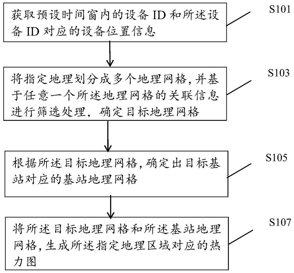
[0017] Specifically as figure 1 As shown, the method may include the following steps:

[0018] S101. Obtain a device ID within a preset time window and device location information corresponding to the device ID;

[0019] Specifically, the device ID refers to the unique identification code of the device connected to the target base station, wherein the target base station refers to any base station in a specified geographical area, and the base station is a fixed base station or a mobile base station, that is, a pseudo base station .

[0020] The device location information includes at least a geographic hash grid corresponding to the device ID;

[0021] Specifically, the preset time window refers to the time interval before the current time node, and the range of the preset time window is 1-3 months, wherein, the preset time window in this embodiment is 1 month , which can ensure the accuracy of data and calculation efficiency.

[0022] S103. Divide the specified geography...

Embodiment 2

[0061] On the basis of Embodiment 1, the method described in Embodiment 2 may include the following steps:

[0062] S101. Obtain a device ID within a preset time window and device location information corresponding to the device ID;

[0063] S103. Divide the specified geography into multiple geographic grids, and perform screening processing based on the associated information of any one of the geographic grids to determine a target geographic grid;

[0064] S105. Determine the base station geographic grid corresponding to the target base station according to the target geographic grid;

[0065] S107. Using the target geographic grid and the base station geographic grid, generate a heat map corresponding to the specified geographic area.

[0066] Specifically, before the step S101, it also includes:

[0067] S100. Update the device ID and device location information corresponding to the device ID;

[0068] Specifically, the device ID and the device location information corr...


PUM


Abstract

The invention discloses a thermodynamic diagram generation method based on a base station coverage area, electronic equipment and a medium. The method comprises the following steps: collecting an equipment ID in a preset time window and equipment position information corresponding to the equipment ID; dividing the specified geography into a plurality of geographic grids, and performing screening processing based on the associated information of any geographic grid to determine a target geographic grid; determining a base station geographic grid corresponding to a target base station according to the target geographic grid; generating a thermodynamic diagram corresponding to the specified geographic area according to the target geographic grid and the base station geographic grid; the method can accurately determine the coverage range of the base station, and facilitates the adjustment of the layout and orientation of the base station according to the coverage range of the base station.

Description

technical field [0001] The present invention relates to the technical field of regional message processing, and in particular to a method for generating a thermal map based on a base station coverage area, electronic equipment and a medium. Background technique [0002] In the prior art, operators use triangulation to determine the coverage of base stations, which has low accuracy and cannot accurately obtain the number of devices within the range of the base station, which is convenient for adjusting the layout and orientation of the base station according to the coverage of the base station; , the operator cannot accurately obtain the coverage of the pseudo base station. Contents of the invention [0003] In order to solve the problems of the prior art, it is possible to accurately determine the coverage of the base station, which includes pseudo base stations, so that the layout and orientation of the base station can be adjusted according to the coverage of the base st...

Claims


Application Information

Patent Timeline
Patent Type & Authority Applications(China)
IPC IPC(8): H04W16/24H04W4/021
CPCH04W16/24H04W4/021Y02D30/70
Inventor 方毅吕繁荣尹祖勇孙勇韬周琦
Owner 杭州云深科技有限公司
Learn More