Busbar structure for capacitor

A technology for busbars and capacitors, which is applied in the direction of wire-wound capacitors, fixed capacitor parts, fixed capacitor leads, etc., which can solve problems such as vibration resistance obstacles, drop-off position accuracy, and deterioration, so as to improve vibration resistance and suppress resonance. Effect

Active Publication Date: 2021-12-17
NICHICON CAPACITOR LTD
View PDF6 Cites 0 Cited by
  • Summary
  • Abstract
  • Description
  • Claims
  • Application Information

AI Technical Summary

Problems solved by technology

[0007] However, the capacitor described in Patent Document 1 only has a structure in which a protrusion provided on the insulating plate is fitted into a hole provided on the opposing plate, so the fitting strength is often insufficient, and the first opposing plate, the insulating plate, etc. and the second opposing plate structure and the tendency of the natural frequency of the adjacent parts close to each other to shift to the lower side, which may hinder the vibration resistance
In addition, depending on the fitting conditions, there may be a problem that the convex part may fall out of the hole unexpectedly in the direction perpendicular to the plate surface, and the problem of poor positional accuracy may occur.
[0008] Here, for the relative positioning of the three components of the pair of opposing plates and the insulating plate in the direction perpendicular to the plate surface, it is also conceivable to use fastening components such as bolts and nuts to clamp the three components, but This fastening work not only complicates the manufacturing process, but also the facing plate portion, which is a thin plate-shaped body, may be deformed by the fastening work, resulting in a decrease in positional accuracy.

Method used


Image

  • Busbar structure for capacitor
  • Busbar structure for capacitor
  • Busbar structure for capacitor

Examples


no. 1 example

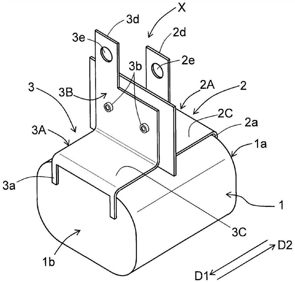
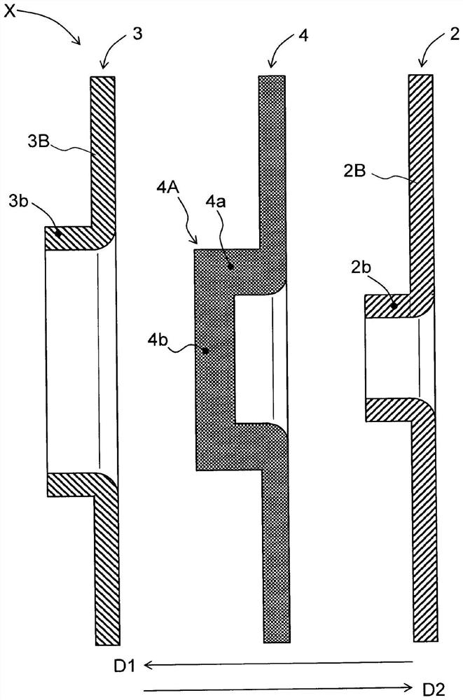
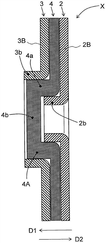
[0043] exist figure 1 ˉ image 3Among them, 1 is the capacitor element, 1a, 1b are the electrodes of the first polarity and the second polarity at both axial ends of the capacitor element 1, 2 is the first bus bar, 3 is the second bus bar, 2A is the first The first main body plate part in the bus bar 2, 3A is the second main body plate part in the second bus bar 3, 2B is the first opposite plate part, and 3b is the second opposite plate part. The main body plate portions 2A, 3A have an L-shaped bent shape, and the opposing plate portions 2B, 3B are part of the main body plate portions 2A, 3A. 2b is the first fitting portion (flange portion) in the first opposing plate portion 2B, 3B is the second fitting portion (burring portion) in the second opposing plate portion 3B, 4 is an insulating plate, and 4A is an insulating plate. The bulge in plate 4 (in figure 2 and image 3 The middle is the cylindrical part with a cover), D1 is the first direction, and D2 is the second dir...

no. 2 example

[0058] In the second embodiment involved Figure 5 and Figure 6 middle, 3b 1 is the conical part in the second fitting part 3b, 3b 2 For the top plate part, 3b 3 is a cylindrical part, 4A' is a bulging part in the insulating plate 4, 4c is an annular part in the bulging part 4A', 4c 1 is an annular recess, 4d is a bottomed recess, and 4e is a peripheral wall part. Other structures are the same as those of the first embodiment. exist Figure 5 and Figure 6 , and in the first embodiment the figure 1 ˉ image 3 The same reference numerals used in 1 and 2 refer to the same structural elements, and detailed description thereof will be omitted.

[0059] In the above-mentioned first embodiment, the first fitting portion 2b in the first opposing plate portion 2B is fitted into the bulging portion 4A in the insulating plate 4 and the second fitting portion 3b in the second opposing plate portion 3B is fitted in the insulating plate 4. A structure in which the bulging portio...


PUM


Abstract

A busbar structure for a capacitor is provided in which an insulating plate has a bulging portion integrally formed therein and bulging in a first direction from a first opposing plate portion toward a second opposing plate portion. The first opposing plate portion has a first fitting portion integrally formed therein so as to bulge in the first direction. The first fitting portion is fitted in the first direction with respect to one side of the bulging portion of the insulating plate. The second opposing plate portion has a second fitting portion integrally formed therein so as to bulge in the first direction. The second fitting portion is fitted in a second direction opposite to the first direction with respect to the other side of the bulging portion.

Description

technical field [0001] The present invention relates to a bus bar structure of a capacitor, which is constructed in such a way that the base ends of first and second bus bars are connected to electrodes of capacitor elements, and the floating ends of these first and second bus bars The sides form first and second opposing plate portions facing each other in a posture close to and parallel to each other, and an insulating plate is sandwiched between the two opposing plate portions. Background technique [0002] A pair of bus bars of the P pole (anode) and N pole (cathode) are constructed of conductive metal thin plates. From the viewpoint of low inductance and miniaturization, it has been shown that the opposing plate parts of a pair of bus bars are arranged close to each other in recent years. Propensity. Although a pair of external connection terminal portions of P pole and N pole on the free end side of the two opposing plate portions are mechanically and electrically eng...

Claims


Application Information

Patent Timeline
Patent Type & Authority Applications(China)
IPC IPC(8): H01G4/228H01R25/16
CPCH01G4/228H01R25/16H01G4/32H01G2/06H01G2/04
Inventor 森隆志村上耕之
Owner NICHICON CAPACITOR LTD
Why Eureka
Try Eureka