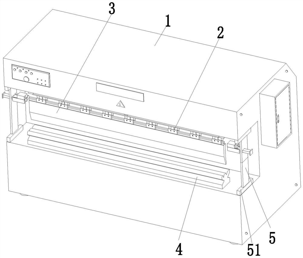
An auxiliary equipment for mold replacement of CNC bending machine
A technology of auxiliary equipment and bending machine, which is applied in the field of auxiliary equipment for mold replacement of CNC bending machines, can solve the problems of reduced fit between the connection structure and the upper mold, difficulty in ensuring lifting stability, and unfavorable installation of the upper mold. Achieve the effects of reduced wear consumption, improved connection efficiency, and reduced time consumption
- Summary
- Abstract
- Description
- Claims
- Application Information
AI Technical Summary
Problems solved by technology
Method used
Image

Examples
Embodiment Construction
[0035] In addition, the following terms are defined based on the functions in the present invention, and can be based on the intention of the user and the operator
[0038] The locking mechanism 25 includes a connecting column 251, a gear 252, a rack 253, a connecting frame 254, a slider 255 and a built-in
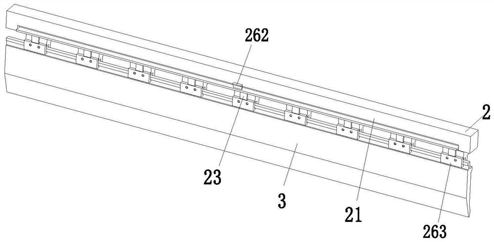
[0039] The positioning mechanism 26 includes a movable plate 261, a hook 262 and a positioning rod 263, and the movable plate 261 and the lifting block 21
[0040] The drag reduction mechanism 27 includes a pressure block 271, an extrusion rod 272, an extrusion block 273, an extension block 274, and a drag reduction roller
[0045] By pushing the cylinder 53 to adjust the position of the placing rack 54 and the position of the electric slider 51 to the electric lift plate 52
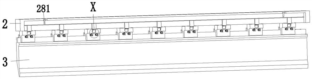
[0046] Drive the linkage plate 282 and the ejector rod 283 to rise as a whole by connecting the cylinder 281, and the upper end of the connecting frame 254 receives the
[0052] Furthermore, it should be ...
PUM
 Abstract
Description
Claims
Application Information
 - R&D
- Intellectual Property
- Life Sciences
- Materials
- Tech Scout
- Unparalleled Data Quality
- Higher Quality Content
- 60% Fewer Hallucinations
Browse by: Latest US Patents, China's latest patents, Technical Efficacy Thesaurus, Application Domain, Technology Topic, Popular Technical Reports.
© 2025 PatSnap. All rights reserved.Legal|Privacy policy|Modern Slavery Act Transparency Statement|Sitemap|About US| Contact US: help@patsnap.com