
Mounting structure of centrally-mounted motor and power-assisted bicycle

A technology of installation structure and mid-mounted motor, which is applied in vehicle parts, transportation and packaging, rider driving, etc. It can solve the problems of deformation, shaking, swinging, and fracture of the motor components of the connecting frame, so as to prevent deformation or even breakage, prevent Shaking and swinging, the effect of improving stability

Pending Publication Date: 2021-12-21
GUANGDONG GOBAO ELECTRONICS TECH CO LTD
View PDF0 Cites 0 Cited by
  • Summary
  • Abstract
  • Description
  • Claims
  • Application Information

AI Technical Summary

Problems solved by technology

However, due to the gap between the motor assembly and the connecting frame, when the two sides of the motor assembly are fastened to the connecting frame by bolts, if the pre-tightening force of the bolts on both sides is too large, large gaps will be generated on both sides of the motor assembly. In addition, the bolts are usually made of steel, and the motor components and connecting frames are usually made of aluminum alloy or magnesium alloy. The rigidity of the motor components and connecting frames is less than that of the bolts, resulting in deformation of the connecting frame or motor components. , or even broken, affecting the service life of the mid-mounted motor
If the pre-tightening force of the bolts is too small, the fixation between the motor assembly and the connecting frame will be unstable, the motor assembly will easily loosen, and shaking and swinging will occur during riding

Method used


Image

  • Mounting structure of centrally-mounted motor and power-assisted bicycle
  • Mounting structure of centrally-mounted motor and power-assisted bicycle
  • Mounting structure of centrally-mounted motor and power-assisted bicycle

Examples


Embodiment Construction

[0038] In order to make the technical problems solved by the present invention, the technical solutions adopted and the technical effects achieved clearer, the technical solutions of the present invention will be further described below in conjunction with the accompanying drawings and through specific implementation methods.

[0039] In the description of the present invention, unless otherwise clearly specified and limited, the terms "connected", "connected" and "fixed" should be understood in a broad sense, for example, it can be a fixed connection, a detachable connection, or an integrated ; It can be a mechanical connection or an electrical connection; it can be a direct connection or an indirect connection through an intermediary, and it can be the internal communication of two components or the interaction relationship between two components. Those of ordinary skill in the art can understand the specific meanings of the above terms in the present invention in specific si...


PUM


Abstract

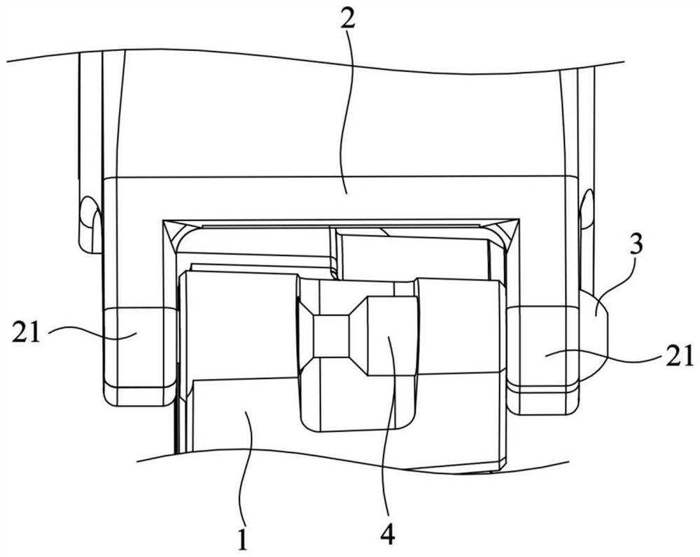
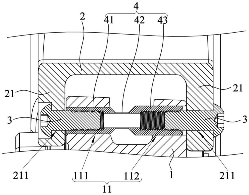
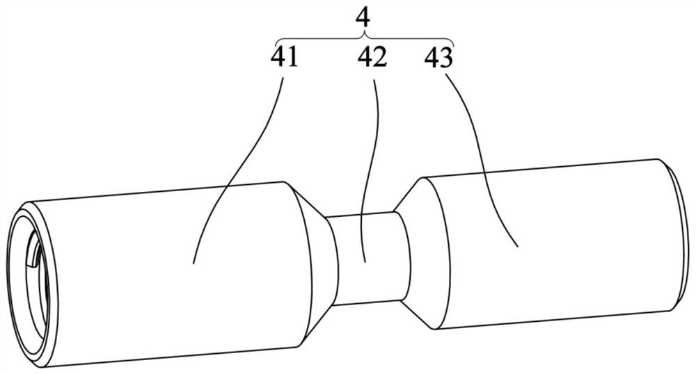
The invention relates to the technical field of power-assisted bicycles, in particular to a mounting structure of a centrally-mounted motor and a power-assisted bicycle. The mounting structure of the centrally-mounted motor comprises a motor assembly, a connecting frame, fasteners and a stretching protection sleeve, a through mounting hole is formed in the motor assembly, the connecting frame comprises two connecting arms located at the two ends of the mounting hole in the length direction respectively, the stretching protection sleeve is arranged in the mounting hole in a penetrating mode, and the two ends of the stretching protection sleeve are connected with the fasteners. The fasteners penetrate through the connecting arms and are fixed to the stretching protective sleeve so as to fix the motor assembly and the connecting frame. Due to the fact that the stretching protection sleeve can be stretched and deformed under the action of the pre-tightening force of the fasteners, compensation is provided for the gap between the motor assembly and the connecting frame, the motor assembly and the connecting frame are prevented from being deformed and even broken under the action of the pre-tightening force, and protection on the motor assembly and the connecting frame is improved. The power-assisted bicycle adopts the mounting structure of the centrally-mounted motor so that the motor assembly and the frame are stably fixed, and the protection on the motor assembly is improved.

Description

technical field [0001] The invention relates to the technical field of power-assisted bicycles, in particular to an installation structure of a central motor and a power-assisted bicycle. Background technique [0002] The power assist bicycle is a new type of transportation with a power assist system that can realize the integration of human riding and electric power assist. The power-assisted bicycle is provided with a central motor, and the central motor is fixed on the vehicle frame, thereby providing power assistance for the power-assisted bicycle. [0003] In the prior art, when the central motor is installed on the vehicle frame, in order to prevent the central motor from shaking and swinging on the vehicle frame during riding, usually both sides of the motor assembly are fixed to the vehicle frame by bolts. on a fixed link. However, in the actual processing and manufacturing process, there is a gap between the motor assembly and the connecting frame due to tolerance...

Claims


Application Information

Patent Timeline
Patent Type & Authority Applications(China)
IPC IPC(8): B62M6/40
CPCB62M6/40
Inventor 张秋阳高常辉
Owner GUANGDONG GOBAO ELECTRONICS TECH CO LTD
Learn More