End lead head forming device for steel wire rope

A forming device and steel wire rope technology, applied in the binding of ends, textiles and papermaking, textile cables, etc., can solve the problems of high cost, waste, unsuitable for home use, etc., and achieve the effect of rapid prototyping, simple operation and convenient use

Pending Publication Date: 2021-12-21
CHANGXING DUZUN INTELLIGENT TECH CO LTD
View PDF0 Cites 0 Cited by
  • Summary
  • Abstract
  • Description
  • Claims
  • Application Information

AI Technical Summary

Problems solved by technology

[0003] When the wire rope is in use, it is usually necessary to fix the joint at the end of the wire rope to realize the end limit. At present, the method of fixing with a lock is usually used. However, this method is not beautiful enough when used, and is not suitable for home use. For example, the wire rope used on the lifting clothes hanger usually adopts the method of fixing lead weight at the end. This fixing method makes it impossible for workers to fix the lead weight at the end of the wire rope again during maintenance, and usually locks are used. It is fixed at the end of the wire rope, which will affect the effect of maintenance, causing many users to be unwilling to repair when the wire rope is damaged, and directly replace it, which not only costs high, but also produces huge waste

Method used


Image

  • End lead head forming device for steel wire rope
  • End lead head forming device for steel wire rope
  • End lead head forming device for steel wire rope

Examples


Embodiment 1

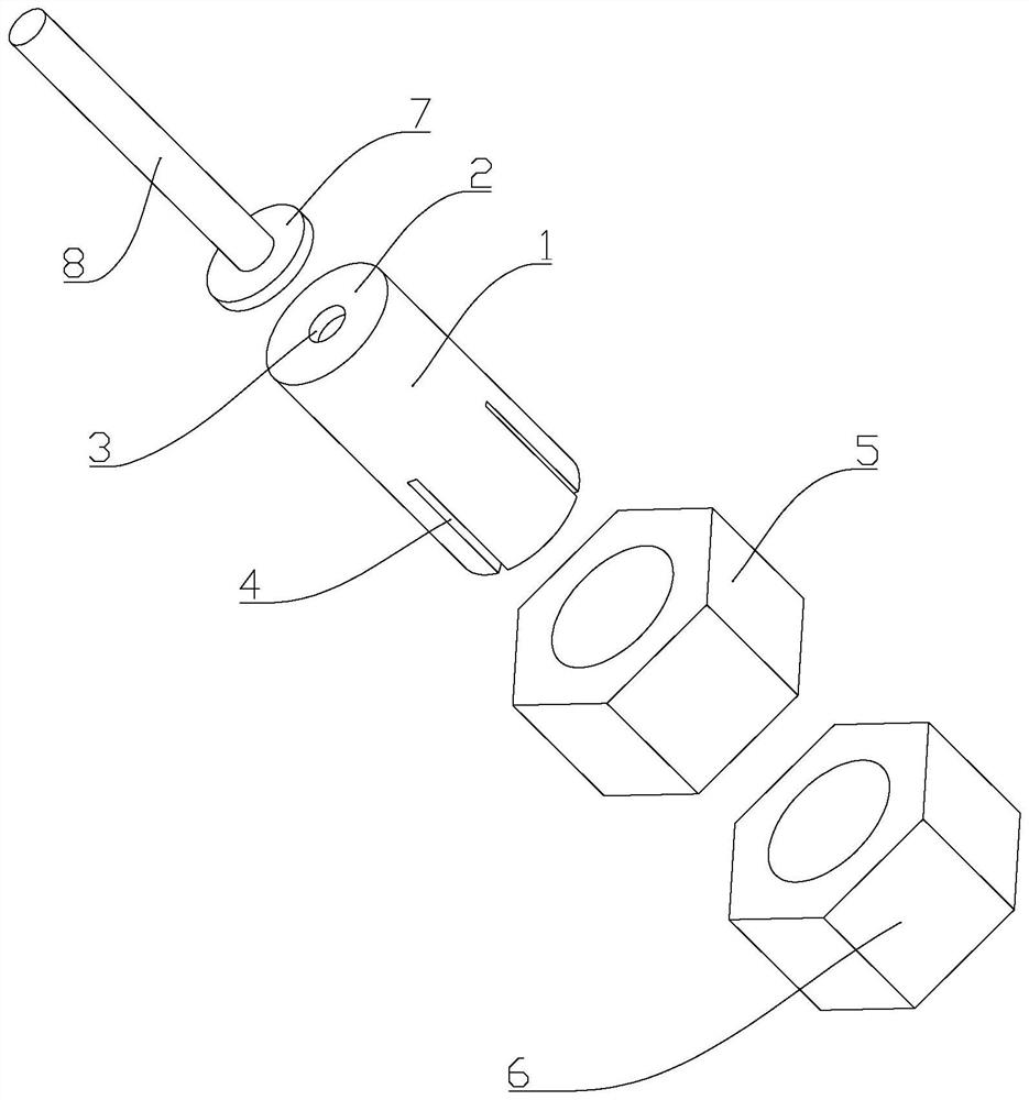
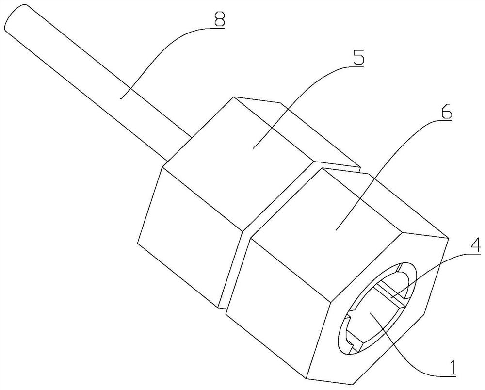
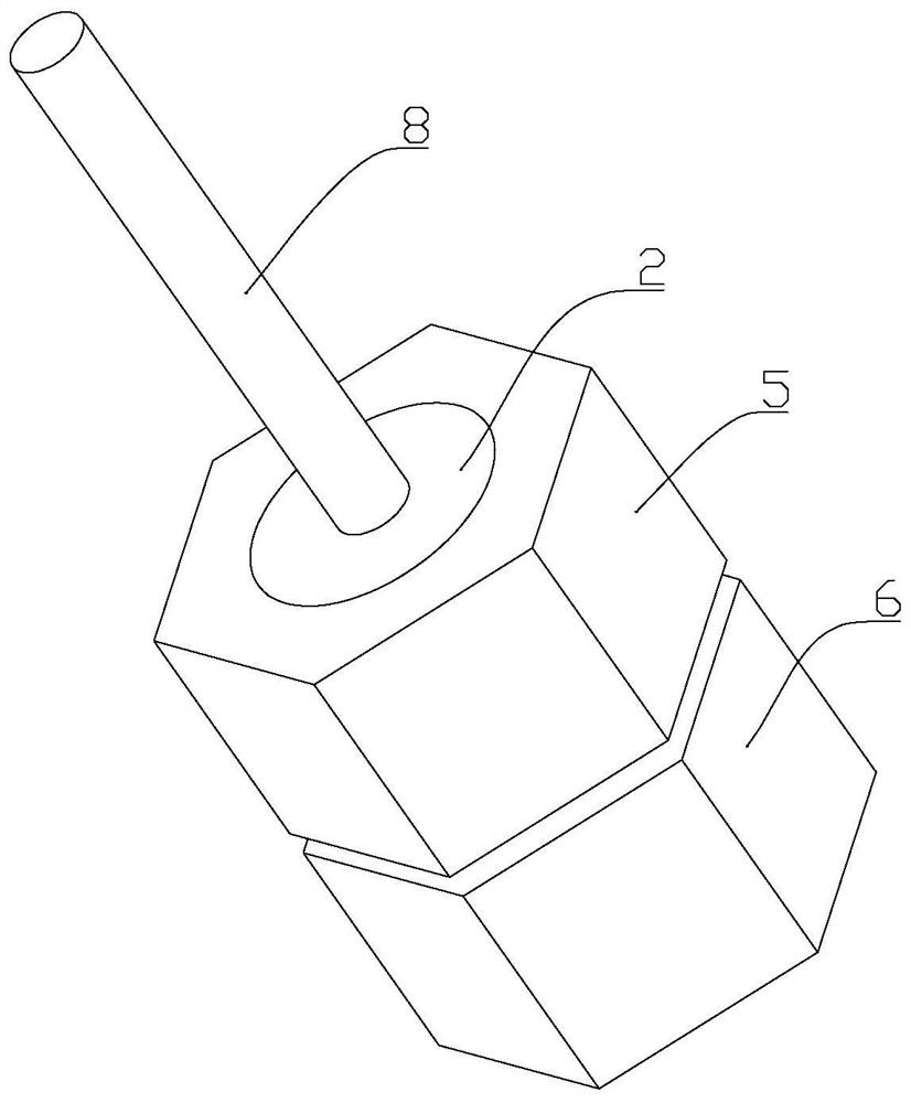
[0017] Such as figure 1 , 2 , 3, a lead forming device at the end of a steel wire rope, comprising a round tube 1, the outer arc surface of the round tube 1 is provided with threads, and one end of the round tube 1 is fixed with a sealing plate 2, the The center of the sealing plate 2 is provided with a through hole 3 coaxial with the round tube 1, and the other end of the round tube 1 relative to the sealing plate 2 is provided with at least one chute 4 in the axial direction of the round tube 1. The outer sides of the two ends of the tube 1 are respectively matched with a first nut 5 and a second nut 6, and the inside of the round tube 1 is provided with a top block 7 that slides axially along the round tube 1, and the top block 7 A push rod 8 is fixed at the end facing the sealing plate 2 in the center, and the push rod 8 is in clearance fit with the through hole 3 .

[0018] The other end of the round tube 1 relative to the sealing plate 2 is provided with four sliding s...


PUM


Abstract

The invention discloses an end lead head forming device for a steel wire rope. The device comprises a round pipe; threads are arranged on the outer side arc face of the round pipe; a sealing plate is fixed to one end of the round pipe; a through hole coaxial with the round pipe is formed in the center of the sealing plate; at least one sliding groove is formed in the other end, opposite to the sealing plate, of the round pipe in the axial direction of the round pipe; a first nut and a second nut are arranged on the outer sides of the two ends of the round pipe in a matched mode respectively; an ejector block sliding in the axial direction of the round pipe is arranged in the round pipe; an ejector rod is fixed to the end, facing the sealing plate, of the center of the ejector block; and the ejector rod is in clearance fit with the through hole. According to the invention, a lead head at the end of the steel wire rope is rapidly formed, the problems in the background technology are effectively solved, and the device is easy to operate and convenient to use.

Description

technical field [0001] The invention relates to a lead head forming device at the end of a steel wire rope. Background technique [0002] The steel wire rope is a spiral steel wire bundle twisted together with steel wires whose mechanical properties and geometric dimensions meet the requirements according to certain rules. The steel wire rope is composed of steel wire, rope core and lubricating grease. The steel wire rope is first twisted into strands by multi-layer steel wires, and then twisted into a helical rope by a certain number of strands with the rope core as the center. In material handling machinery, it is used for lifting, pulling, tensioning and carrying. The steel wire rope has high strength, light weight, stable operation, and is not easy to break suddenly, and the operation is reliable. [0003] When the wire rope is in use, it is usually necessary to fix the joint at the end of the wire rope to realize the end limit. At present, the method of fixing with a ...

Claims


Application Information

Patent Timeline
Patent Type & Authority Applications(China)
IPC IPC(8): D07B9/00
CPCD07B9/00
Inventor 倪武强
Owner CHANGXING DUZUN INTELLIGENT TECH CO LTD
Why Eureka
Try Eureka