
Solar safety monitoring equipment

A technology of safety monitoring and monitoring equipment, which is applied in mechanical equipment, supporting machines, transportation and packaging, etc., and can solve problems such as inability to achieve coverage without dead angles, inability to adjust monitoring intervals, and inconvenient wiring

Pending Publication Date: 2021-12-21
湖南金鹤科技有限公司
View PDF11 Cites 0 Cited by
  • Summary
  • Abstract
  • Description
  • Claims
  • Application Information

AI Technical Summary

Problems solved by technology

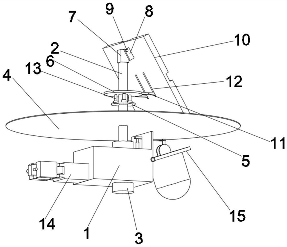
[0002] When intelligent network monitoring has been widely popularized in the streets and alleys, there are still many important security areas that cannot be monitored due to inconvenient wiring. The coverage without dead spots cannot be achieved. In traditional monitoring equipment, the monitoring camera is connected to the battery and the battery through the power line. The transmission equipment, after improvement, uses solar energy to supply energy for the monitoring equipment, and the image information collected by the camera is directly transmitted to the smart device through wireless signal transmission, that is, a wireless monitoring all-in-one machine that can operate independently. Nowadays, with the new solar energy The development of solar power generation realizes solar monitoring, while the position of the solar panel in the existing solar monitoring is fixed
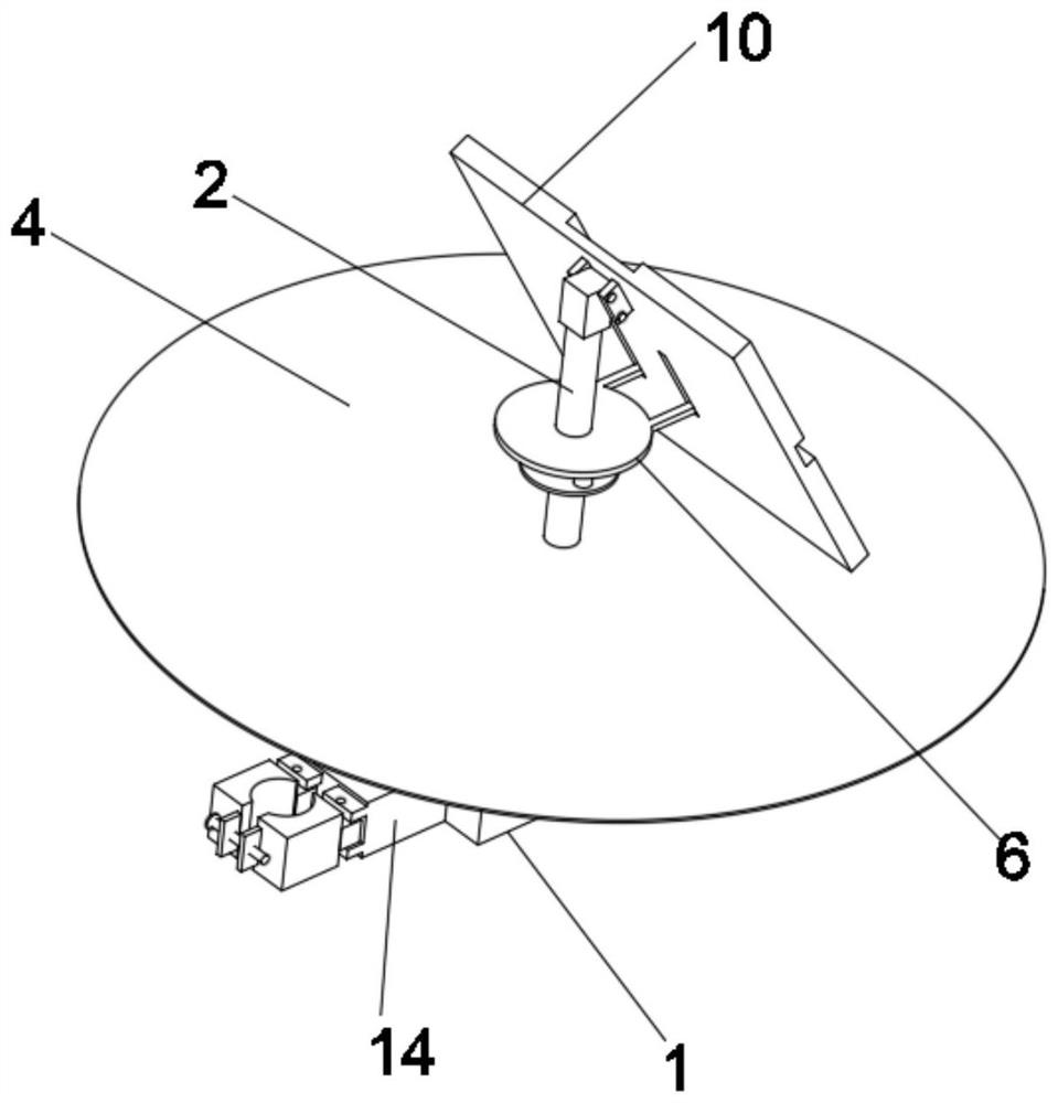
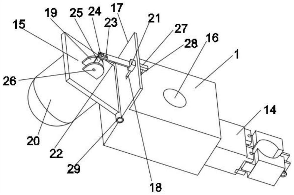
[0003] Most of the existing solar monitoring equipment is fixed, and it is difficult to adjust the angle of the solar panel according to the demand to achieve the maximum capture rate of light energy; most of the monitoring equipment is also fixed, and cannot be adjusted according to the demand to obtain a wider range of monitoring intervals; The installation of monitoring equipment needs to be fixed by more bolts, which is cumbersome

Method used


Image

  • Solar safety monitoring equipment
  • Solar safety monitoring equipment
  • Solar safety monitoring equipment

Examples


Embodiment Construction

[0026] The following will clearly and completely describe the technical solutions in the embodiments of the present invention with reference to the accompanying drawings in the embodiments of the present invention. Obviously, the described embodiments are only some, not all, embodiments of the present invention. Based on the embodiments of the present invention, all other embodiments obtained by persons of ordinary skill in the art without making creative efforts belong to the protection scope of the present invention.

[0027] In the description of the present invention, it should be noted that the terms "upper", "lower", "inner", "outer", "front end", "rear end", "both ends", "one end", "another end" The orientation or positional relationship indicated by etc. is based on the orientation or positional relationship shown in the drawings, and is only for the convenience of describing the present invention and simplifying the description, rather than indicating or implying that ...


PUM


Abstract

The invention discloses solar safety monitoring equipment. The solar safety monitoring equipment comprises a control box and a central shaft, wherein the central shaft is rotatably connected to the control box; a solar panel is movably mounted at the top end of the central shaft; a solar panel longitudinal angle adjusting mechanism is arranged on the solar panel and the central shaft; a solar panel rotating angle adjusting mechanism is arranged on the outer wall of a part, which is positioned in the control box, of the central shaft; a mounting mechanism is arranged on one side of the control box; the other side of the control box is rotatably connected with a second mounting plate; monitoring equipment is mounted on the lower surface of the second mounting plate; and a monitoring equipment angle adjusting mechanism is arranged on the upper surface of the second mounting plate. By a series of structures, the angle of the solar panel can be adjusted as needed to achieve the maximum capture rate of light energy; the monitoring equipment can be adjusted as needed to obtain a monitoring interval in a large range; and the monitoring equipment can be mounted simply by bolts.

Description

technical field [0001] The invention relates to the technical field of safety monitoring, in particular to a solar energy safety monitoring device. Background technique [0002] When intelligent network monitoring has been widely popularized in the streets and alleys, there are still many important security areas that cannot be monitored due to inconvenient wiring. The coverage without dead spots cannot be achieved. In traditional monitoring equipment, the monitoring camera is connected to the battery and the battery through the power line. The transmission equipment, after improvement, uses solar energy to supply energy for the monitoring equipment, and the image information collected by the camera is directly transmitted to the smart device through wireless signal transmission, that is, a wireless monitoring all-in-one machine that can operate independently. Nowadays, with the new solar energy The development of the invention utilizes solar power generation to realize sola...

Claims


Application Information

Patent Timeline
Patent Type & Authority Applications(China)
IPC IPC(8): F16M11/12F16M11/18H02S20/30H02J7/35H04N7/18
CPCF16M11/12F16M11/18H02S20/30H02J7/35H04N7/18Y02E10/50
Inventor 董名球黄罗通董佳欣向丽虹董佳华
Owner 湖南金鹤科技有限公司
Learn More