LED lighting module

A technology of LED lighting and LED light board, which is applied in the field of LED lighting, can solve problems such as low production efficiency, lower protection level, and inability to move modules, and achieve the effects of improving production efficiency, reducing impact, and simple operation

Pending Publication Date: 2021-12-21
CECEP LATTICELIGHTING
View PDF0 Cites 0 Cited by
  • Summary
  • Abstract
  • Description
  • Claims
  • Application Information

AI Technical Summary

Problems solved by technology

[0003] The invention aims to solve the technical problems of low production efficiency caused by the inability to move the modules after dispensing and the decrease of protection level caused by air trapping when the protective glass is pressed on the lens cover.

Method used


Image

  • LED lighting module
  • LED lighting module
  • LED lighting module

Examples


Embodiment 1

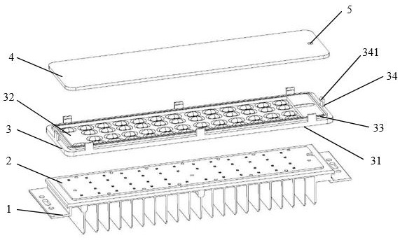
[0027] Please refer to the attached Figures 1 to 3 , an LED lighting module, including a heat sink 1, an LED lamp board 2, a lens cover 3 and a protective glass 4, the lens cover 3 has an inner surface 31 close to the LED lamp board 2 and close to the protective glass 4 The outer surface 32 of the glass 4 .

[0028] Further, the protective glass 4 is flat glass 41 .

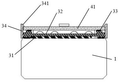
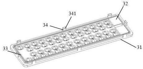
[0029] Further, the inner surface 31 and the outer surface 32 are respectively provided with a ring of glue grooves 33, which are used for bonding with the heat sink 1 and the flat glass 41 after filling with liquid silica gel.

[0030] Further, the flat glass 41 is provided with a through hole 5, which is used to release the air between the flat glass 41 and the lens cover 3 when bonding to avoid the influence of trapped air. The diameter is 1 mm.

[0031] Further, the outer surface 32 of the lens cover 3 is provided with several buckle-type connectors 34 on the peripheral edge, and the buckles 341 of the bu...

Embodiment 2

[0034] Please refer to the attached image 3 and attached Figure 4 , an LED lighting module, including a heat sink 1, an LED lamp board 2, a lens cover 3 and a protective glass 4, the lens cover 3 has an inner surface 31 close to the LED lamp board 2 and close to the protective glass 4 The outer surface 32 of the glass 4 .

[0035] Further, the protective glass 4 is a molded curved glass 42, and the molded curved glass 42 has a circle of grooves 421 around its edges.

[0036] Further, the inner surface 31 and the outer surface 32 are respectively provided with no less than a circle of glue grooves 33, which are used for filling liquid silica gel, respectively, with the heat sink 1 and the molded curved glass 42. bonding.

[0037] Further, the molded curved glass 42 is provided with a through hole 5, which is used to release the air between the molded curved glass 42 and the lens cover 3 when they are bonded, so as to avoid the influence of trapped air. 5 has a diameter of...

Embodiment 3

[0042] Please refer to the attached figure 1 and attached Figure 5 , an LED lighting module, including a heat sink 1, an LED lamp board 2, a lens cover 3 and a protective glass 4, the lens cover 3 has an inner surface 31 close to the LED lamp board 2 and close to the protective glass 4 The outer surface 32 of the glass 4 .

[0043] Further, the protective glass 4 is flat glass 41 .

[0044] Further, two circles of gluing grooves 33 are respectively arranged around the inner surface 31 and the outer surface 32 , which are used for bonding with the heat sink 1 and the flat glass 41 after being filled with liquid silica gel.

[0045] Further, the flat glass 41 is provided with a through hole 5, which is used to release the air between the flat glass 41 and the lens cover 3 when bonding to avoid the influence of trapped air. The diameter is 2mm.

[0046] Further, the outer surface 32 of the lens cover 3 is provided with several buckle-type connectors 34 on the peripheral edge...


PUM

PropertyMeasurementUnit
diameteraaaaaaaaaa

Abstract

The invention discloses an LED lighting module. The LED lighting module comprises a cooling fin, an LED lamp panel, a lens surface cover and protective glass, the lens surface cover is provided with an inner surface close to the LED lamp panel and an outer surface close to the protective glass, and the periphery of the inner surface and the periphery of the outer surface are each provided with at least one circle of groove used for being filled with liquid silica gel; and a plurality of buckle type connecting pieces are arranged on the edge of the outer surface of the lens surface cover and used for fixing protective glass, and through holes are formed in the protective glass and used for releasing air trapped when the protective glass and the lens surface cover are bonded. The lighting module has the beneficial effects that: installation is easy and convenient, moving and overturning are achieved after glue dispensing, the protective glass is not prone to displacement, the production efficiency is high, and the situation that the protection grade is easy to decrease due to air trapping is reduced.

Description

technical field [0001] The invention relates to the field of LED lighting, in particular to an LED lighting module. Background technique [0002] In order to facilitate installation and maintenance, traditional LED street lamps use modular LED modules to assemble lamps and lanterns. It has become a common practice for manufacturers. Because liquid silicone is used to replace the sealing ring, it has the advantages of fast operation and better sealing performance. However, due to the need for curing During the production process, the modules after dispensing are dislocated, or the glue is left to wait for the glue to cure after dispensing, resulting in low production efficiency; and during the glue curing process, due to the gap between the protective glass and the lens cover Due to the influence of trapped air, the protective glass cannot fit tightly with the lens cover, resulting in a lower protection level than the design requirement. Contents of the invention [0003] ...

Claims


Application Information

Patent Timeline
Patent Type & Authority Applications(China)
IPC IPC(8): F21K9/20F21V3/00F21V17/16F21V31/00F21W131/103F21Y105/16F21Y115/10
CPCF21S2/005F21V17/164F21V31/005F21V3/00F21Y2115/10F21Y2105/16F21W2131/103
Inventor 王鹏曾平胡俊
Owner CECEP LATTICELIGHTING
Why Eureka
Try Eureka