Rotary stripping rate tester and using method

A peel rate and tester technology, applied in the field of rotary peel rate testers, can solve the problems of increased test error, low test efficiency, low accuracy and repeatability of results, and achieves good wear resistance, rich variety Test conditions, the effect of strong versatility

Pending Publication Date: 2021-12-21
OECHSLER PLASTIC PROD TAICANG
View PDF0 Cites 0 Cited by
  • Summary
  • Abstract
  • Description
  • Claims
  • Application Information

AI Technical Summary

Problems solved by technology

[0003] During the implementation of the present invention, we found that the existing peeling rate tester also has the following problems: the first, the existing peeling rate tester preferably tests one sample at a time, and the test efficiency is low. If multiple samples are tested simultaneously , due to the unbalanced force between the samples, it is easy to cause the accuracy and repeatability of the results to be low; second, the existing peeling rate tester applies pressure to the surface of the test piece by weight pressing, and this pressure method is also It will limit the test efficiency. If the surface of the test piece moves too fast relative to the surface of the test cloth, the tester will vibrate obviously, resulting in an increase in the test error; third, the actual environment faced by the product in actual use is very complex and diverse , but the existing tester can only characterize the wear resistance of the product with a single friction material in a conventional environment, which deviates greatly from the actual situation

Method used


Image

  • Rotary stripping rate tester and using method
  • Rotary stripping rate tester and using method
  • Rotary stripping rate tester and using method

Examples


Embodiment 1

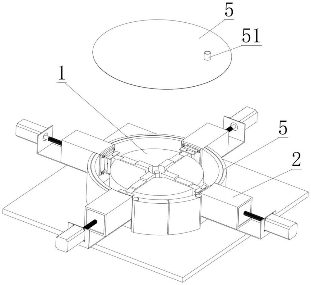
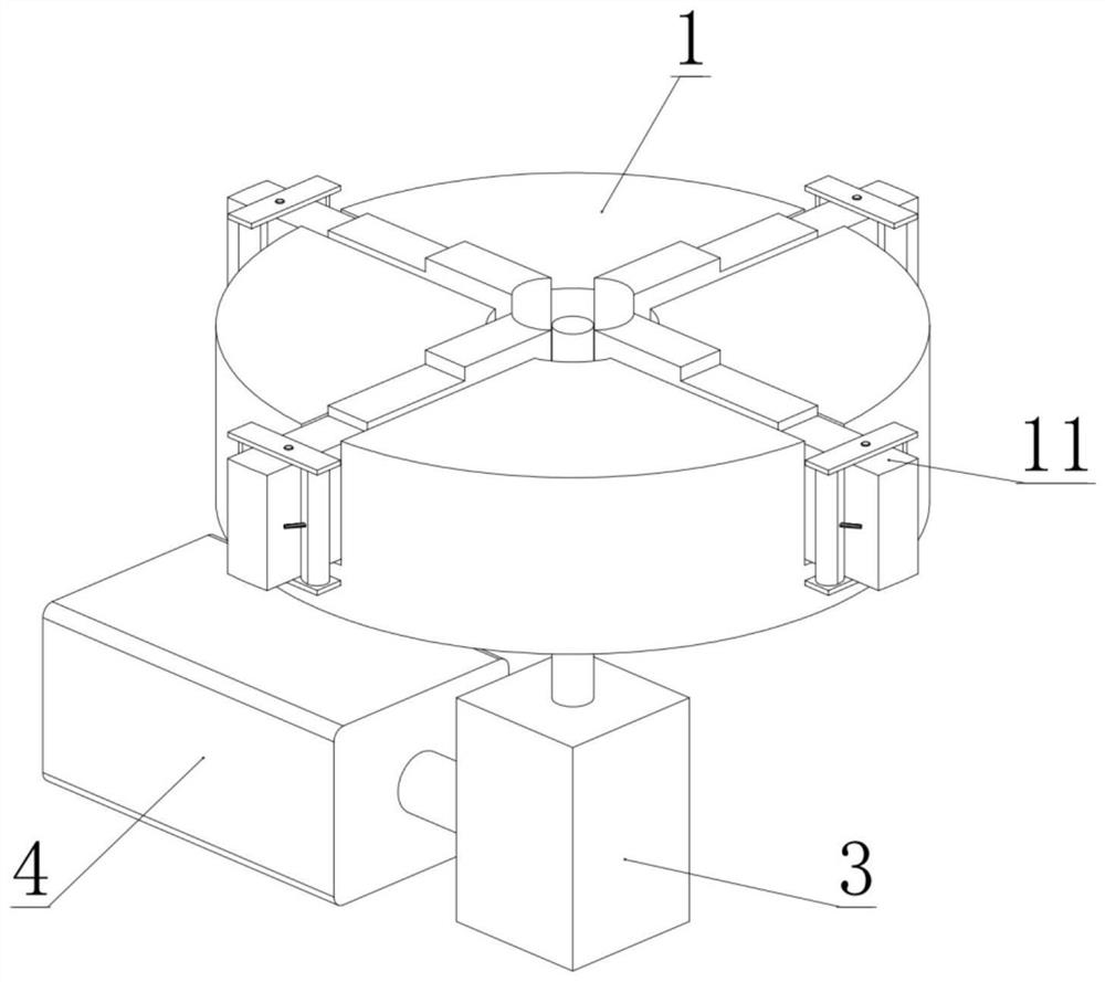
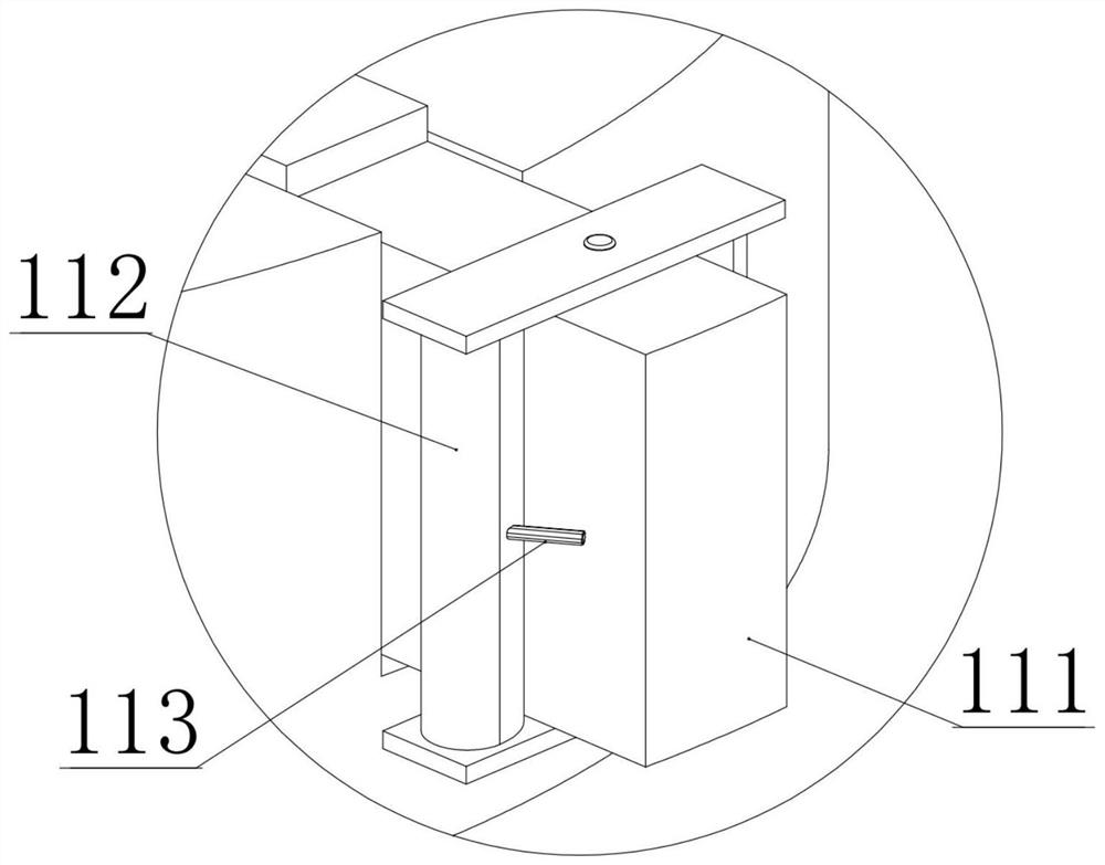
[0036] A rotary peel rate tester such as Figures 1 to 6 As shown, it includes a rotatable turntable 1 and a set of specimen clamping devices 2 distributed around the turntable 1; a set of fixed assemblies 11 that rotate with the turntable 1 are provided on the side of the turntable 1; the fixed assembly 11 can fix the friction material, And make the friction surface of the friction material face the specimen holding device 2; the specimen holding device 2 includes a pressing block 21 that can elastically slide along the radial direction of the turntable 1, and the end face of the pressing block 21 facing the turntable 1 is marked as a pressing end face, The test piece can be fixed on the pressing end surface; the test piece holding device 2 also includes a compression spring 25 that pushes the pressing block 21 to the turntable 1; The portion 29 determines the limit position where the pressing block 21 slides toward the turntable 1 .

[0037] In this embodiment, the fixing a...


PUM


Abstract

The invention belongs to the technical field of surface testing and particularly relates to a rotary stripping rate tester and a using method. The invention provides a rotary stripping rate tester. The rotary stripping rate tester comprises a rotatable turntable and a group of test piece clamping devices distributed around the turntable, a group of fixing assemblies rotating along with the turntable is arranged on the peripheral side of the turntable; the fixing assemblies can fix friction materials and enable friction surfaces of the friction materials to face the test piece clamping devices; the test piece clamping device comprises a pressing block capable of elastically sliding in the radial direction of the rotary disc, an end face, facing the rotary disc, of the pressing block is marked as a press-fit end face, and a test piece can be fixed to the press-fit end face; the test piece clamping device further comprises a pressure spring for pushing the pressure block to the turntable; the test piece clamping device further comprises a limiting part for blocking the pressing block, and the limiting part determines the limiting position of the pressing block sliding towards the rotating disc. The rotary stripping rate tester has advantages of high universality, high test efficiency, rich and adjustable test conditions and the like.

Description

technical field [0001] The invention belongs to the technical field of surface testing, and in particular relates to a rotary peeling rate tester and a usage method. Background technique [0002] The peeling rate tester is a test equipment used to test the wear resistance of the surface layer of the product (such as the coating layer). Usually, the peeling rate tester mainly includes the clamping device of the tested piece, the moving device of the tested piece and the fixing device of the test cloth / sandpaper. The abrasion resistance was evaluated by peeling. [0003] During the implementation of the present invention, we found that the existing peeling rate tester also has the following problems: the first, the existing peeling rate tester preferably tests one sample at a time, and the test efficiency is low. If multiple samples are tested simultaneously , due to the unbalanced force between the samples, it is easy to cause the accuracy and repeatability of the results t...

Claims


Application Information

Patent Timeline
Patent Type & Authority Applications(China)
IPC IPC(8): G01N3/56G01N3/02G01N3/04
CPCG01N3/56G01N3/02G01N3/04
Inventor 潘璇熊志生
Owner OECHSLER PLASTIC PROD TAICANG
Why Eureka
Try Eureka