
Calibration method of linear scanning mechanism for cylindrical visual target

A calibration method and line scan technology, applied in computer parts, image data processing, instruments, etc., can solve the problem that the cost is difficult to control, it is difficult to obtain pictures, and the line scan camera is difficult to be parallel to the cylindrical surface of the workpiece to be measured, etc. problem, to solve the problem of image deformation and avoid high consumption and low efficiency.

Pending Publication Date: 2021-12-21
ZHUHAI FUDAN INNOVATION INST
View PDF0 Cites 0 Cited by
  • Summary
  • Abstract
  • Description
  • Claims
  • Application Information

AI Technical Summary

Problems solved by technology

[0003] Due to mechanical installation and other reasons, it is difficult for the line scan camera to be parallel to the cylindrical surface of the workpiece to be measured, resulting in the deformation of the collected image, and finally it is difficult to obtain pictures that can be used for measurement or defect detection
The existing method is to ensure that the line-scanning camera is parallel to the measuring cylinder through mechanical limit and other means, and set an appropriate speed to obtain an image without deformation. The cost is difficult to control; the second is that the installation requirements are very high, and a small part that is not installed in parallel may cause the line scan camera to fail to work normally; Multiple acquisitions and multiple adjustments, time-consuming, low efficiency and no guarantee of accuracy

Method used


Image

  • Calibration method of linear scanning mechanism for cylindrical visual target
  • Calibration method of linear scanning mechanism for cylindrical visual target
  • Calibration method of linear scanning mechanism for cylindrical visual target

Examples


Embodiment Construction

[0019] In order to make the technical means, creative features, goals and effects achieved by the present invention easy to understand, a method for calibrating a line-scanning mechanism for cylindrical visual objects of the present invention will be described in detail below in conjunction with the embodiments and accompanying drawings.

[0020]

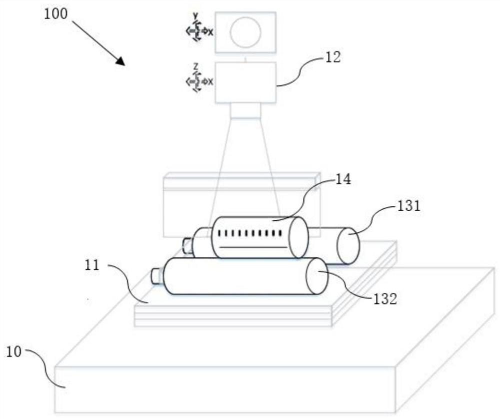
[0021] figure 1 It is a schematic diagram of the line sweep mechanism in the embodiment of the present invention.

[0022] The experimental environment of this embodiment is set on the line scanning mechanism for visually collecting the cylindrical surface of the workpiece, such as figure 1 As shown, the line scanning mechanism 100 has a base 10 , a carrying platform 11 arranged on the base 10 for carrying workpieces, a rotating drive mechanism for driving the workpieces to rotate on the carrying platform 11 , and a line scanning camera 12 .

[0023] The rotating drive mechanism includes a motor (not shown) and a cylinder 131 and...


PUM


Abstract

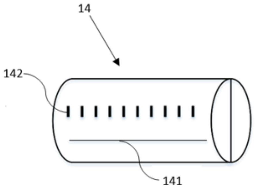
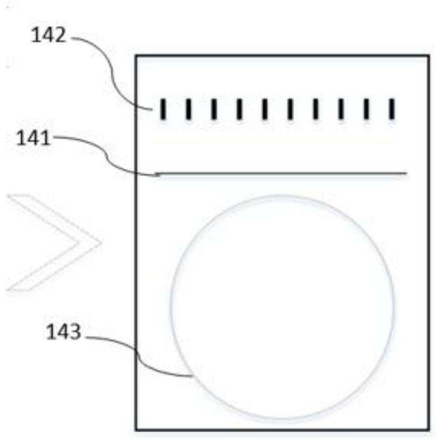
The invention provides a calibration method of a linear scanning mechanism for a cylindrical visual target, which is characterized in that a calibration column is adopted to calibrate the linear scanning mechanism, and a first calibration line, a plurality of second calibration lines perpendicular to the first calibration line and a calibration circle are marked on the cylindrical surface of the calibration column; the method comprises the following steps: firstly, an image acquisition height is set based on a first calibration line graph displayed in an image acquired by a line scanning camera; the first calibration line graph and the projection of the acquisition line of the line scanning camera on the plane of the camera chip form an included angle; the vertical included angle between the acquired first calibration line graph and the projection of the acquisition line on the plane of the camera chip and the multiple of the long axis and the short axis of a calibration circle graph corresponding to a calibration circle of the calibration column are solved according to the pixel position difference of the distance between the second calibration line graph and the pixel position difference; the angle, the included angle and the rotating speed of the bearing platform are sequentially adjusted through the angle and inclination angle adjusting mechanism and the rotating driving mechanism, and calibration is completed.

Description

technical field [0001] The invention belongs to the field of machine vision and relates to a calibration method for a line-scanning mechanism aimed at a cylindrical visual target. Background technique [0002] The line scan camera can capture high-resolution images of objects moving at a constant speed, and is suitable for high-speed or high-resolution image collection. It is also suitable for high-precision detection of curved surfaces such as bearings in industry and flower print detection and measurement of cylindrical product surfaces. [0003] Due to reasons such as mechanical installation, it is difficult for the line scan camera to be parallel to the cylindrical surface of the workpiece to be measured, resulting in the deformation of the collected image, and finally it is difficult to obtain pictures that can be used for measurement or defect detection. The existing method is to ensure that the line-scanning camera is parallel to the measuring cylinder through mechani...

Claims


Application Information

Patent Timeline
Patent Type & Authority Applications(China)
IPC IPC(8): G06T7/80G06K9/20
CPCG06T7/80
Inventor 何良雨许赢月黄浩智
Owner ZHUHAI FUDAN INNOVATION INST
Learn More