Rotating speed estimation and calibration method for near-field turntable target
A rotation speed and target technology, applied in the radar field, can solve the problems of near-field ISAR imaging distortion, estimation of near-field target motion parameters not involved, and achieve the effect of improving computing efficiency
- Summary
- Abstract
- Description
- Claims
- Application Information
AI Technical Summary
Problems solved by technology
Method used
Image
Examples
specific Embodiment approach 1
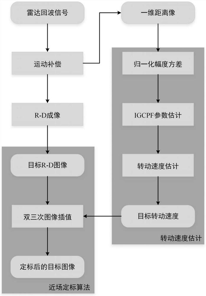
[0037] Specific implementation mode 1: In this implementation mode, a method for estimating and calibrating the rotational speed of a near-field turntable target has a specific process as follows:
[0038] The radar receives the echo signal of the near-field target, performs motion compensation on the signal, converts the target into a turntable target, uses the R-D algorithm to image, and obtains the one-dimensional range image and R-D image of the target respectively. Use the one-dimensional range image of the target to estimate the target rotation speed, calculate the normalized amplitude variance of each distance unit corresponding to the slow time signal, and select the distance unit with distinctive points; integrate the cubic polynomial phase signal of the distance unit The parameters of the generalized cubic phase function (IGCPF) are estimated to obtain the phase coefficients of each order of the signal; the rotation speed of the target is estimated by using each order...
specific Embodiment approach 2
[0047] Specific embodiment two: the difference between this embodiment and specific embodiment one is: in the step two, calculate the one-dimensional distance image S(k n , each distance unit in m) corresponds to the slow time signal The normalized amplitude variance of , to judge whether there is a distinctive point in the distance unit;
[0048] The specific process is:
[0049] Calculate the one-dimensional range image S(k n , each distance unit in m) corresponds to the slow time signal The normalized magnitude variance of , the normalized magnitude variance is defined as
[0050] Among them, E represents the mean value operation; k is the number of certain distance units;
[0051] When the normalized magnitude variance value is less than 0.12, it is preliminarily considered that there are isolated characteristic points in the corresponding distance unit, and the 8- 10 distance units (8, 9 or 10 distance units corresponding to the smallest normalized magnitude vari...
specific Embodiment approach 3
[0053] Specific embodiment three: the difference between this embodiment and specific embodiment one or two is that in the step three, select the distance unit that has a characteristic point in the step two, and use the integral type generalized cubic phase function IGCPF to correspond slowly to the distance unit time signal k (m) Carry out cubic polynomial phase signal parameter estimation, obtain the estimated value of each phase coefficient of signal; Concrete process is:
[0054] Step 31. Assume that the discrete form of the slow-time cubic polynomial phase signal corresponding to the distance unit is s k (m) = σ 0 exp[j(a 1 m+a 2 m 2 +a 3 m 3 )],
[0055] in, M is the length of the azimuth signal, σ 0 is the signal amplitude, a p Indicates the phase coefficient of each order, p=1,2,3; j is the imaginary unit, j 2 =-1;
[0056] Signal s in step 32 and step 31 k The generalized cubic phase function GCPF of (m) is defined as
[0057]
[0058] in,(·) * is ...
PUM
 Abstract
Description
Claims
Application Information
 - R&D
- Intellectual Property
- Life Sciences
- Materials
- Tech Scout
- Unparalleled Data Quality
- Higher Quality Content
- 60% Fewer Hallucinations
Browse by: Latest US Patents, China's latest patents, Technical Efficacy Thesaurus, Application Domain, Technology Topic, Popular Technical Reports.
© 2025 PatSnap. All rights reserved.Legal|Privacy policy|Modern Slavery Act Transparency Statement|Sitemap|About US| Contact US: help@patsnap.com


