Small lamp lifter capable of adjusting load-bearing early warning induction device
A technology of induction device and lifter, which is applied in the field of compact lamp lifter, can solve the problems of affecting the use of equipment, inefficient processing methods, and the range setting function of the lifter without considering the range setting function, so as to reduce wear and tear, achieve good wiring effect, and avoid Effects of security incidents
- Summary
- Abstract
- Description
- Claims
- Application Information
AI Technical Summary
Problems solved by technology
Method used
Image

Examples
Embodiment Construction
[0030] The following will clearly and completely describe the technical solutions in the embodiments of the present invention with reference to the accompanying drawings in the embodiments of the present invention. Obviously, the described embodiments are only some, not all, embodiments of the present invention. Based on the embodiments of the present invention, all other embodiments obtained by persons of ordinary skill in the art without making creative efforts belong to the protection scope of the present invention.
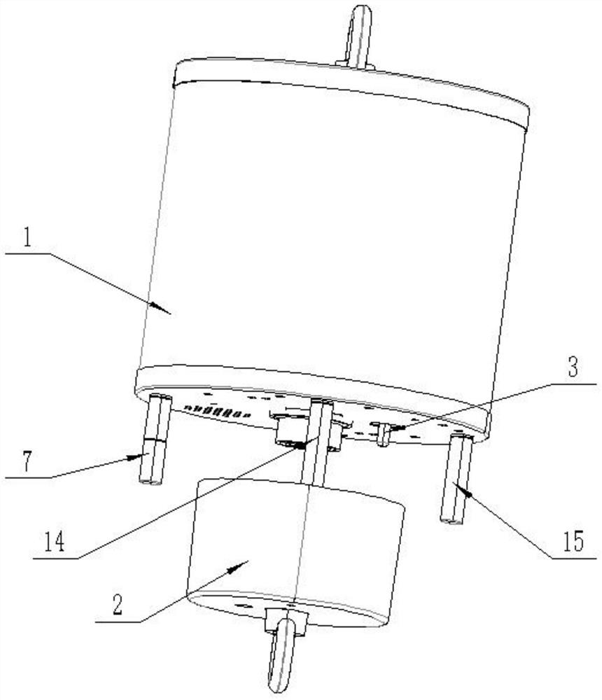
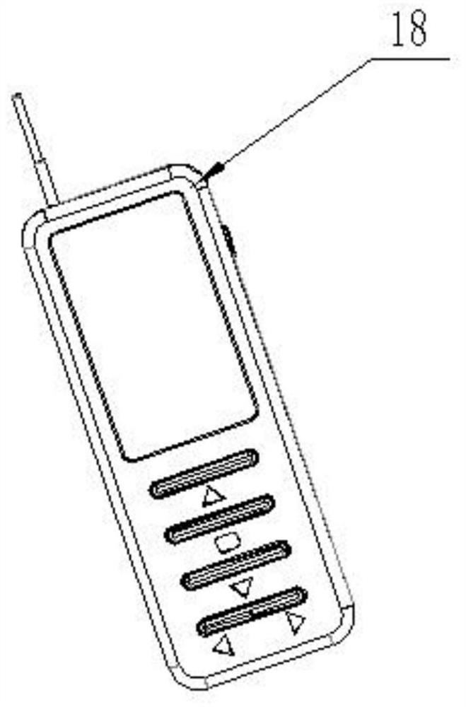
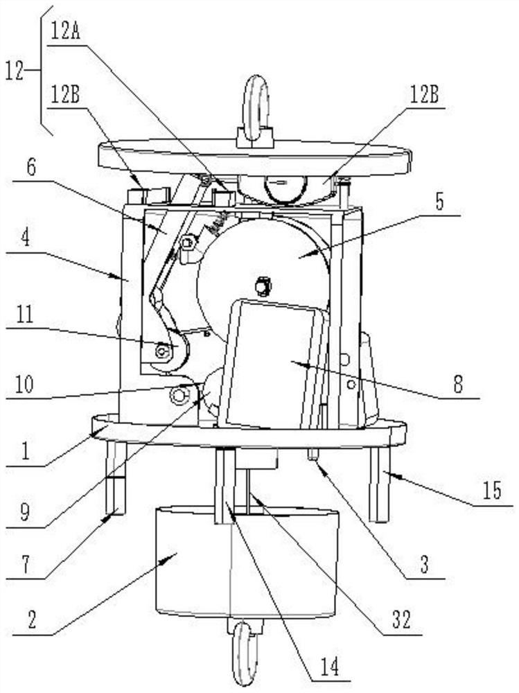
[0031] see Figure 1-7 , the present invention provides a technical solution: a compact lamp lifter with an adjustable load-bearing early warning sensing device, including a host 1, a hook base 2, a steel wire 32 and a remote controller 18, and a control box is fixedly installed inside the host 1 31. The remote controller 18 is provided with a no-load operation control module inside, the lower end of the host 1 is fixedly installed with a trigger switch 3 , th...
PUM
 Abstract
Description
Claims
Application Information
PatSnap Eureka turns technology decisions into work you can execute. Powered by our Innovation Knowledge Graph, it runs expert workflows across engineering, life sciences, materials and intellectual property. Get your review-ready output in minutes.


