Convenient current terminal replacement system

A current terminal, convenient technology, applied in the direction of circuits, electrical components, coupling devices, etc., can solve the problem that the current terminal is difficult to replace

Active Publication Date: 2021-12-21
GUIZHOU POWER GRID CO LTD
View PDF0 Cites 0 Cited by
  • Summary
  • Abstract
  • Description
  • Claims
  • Application Information

AI Technical Summary

Problems solved by technology

[0004] In view of the problem that the above-mentioned existing current terminals are difficult to replace, the present invention is proposed

Method used


Image

  • Convenient current terminal replacement system
  • Convenient current terminal replacement system
  • Convenient current terminal replacement system

Examples


Embodiment 1

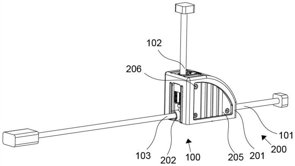
[0027] refer to Figure 1-4 , a convenient current terminal replacement system includes a main body assembly 100, including a main line 101, a backup line 102, and a terminal line 103 connected to the main line 101; The main interface 202 , the active interface 203 cooperating with the main line 101 and the backup line 102 , and the conversion piece 300 arranged in the casing 201 and cooperating with the active interface 203 .

[0028] Specifically, the main body assembly 100 includes a main line 101, a backup line 102, and a terminal line 103 connected to the main line 101; The active interface 203 that cooperates with the line 101 and the standby line 102, and the conversion piece 300 that is arranged in the casing 201 and cooperates with the active interface 203, the conversion piece 300 completes the lossless line switching by making the active interface 203 quickly move to the standby line 102, the main The line 101 and the terminal line 103 are always connected through ...

Embodiment 2

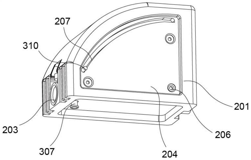
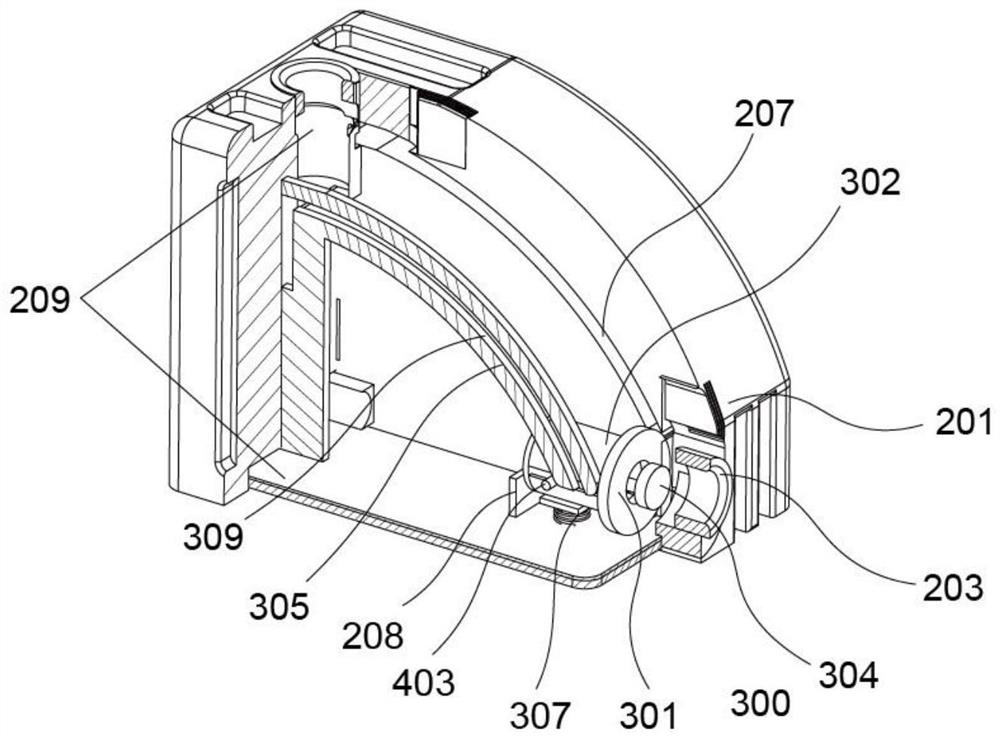
[0031] refer to Figure 1-4 , this embodiment is different from the first embodiment in that: the main interface 202 and the movable interface 203 are respectively arranged at the left and right ends of the casing 201, and the backup line 102 is arranged at the top of the casing 201; A mounting plate 204 and a second mounting plate 205, the first mounting plate 204 and the second mounting plate 205 are provided with more than two mounting holes 206; The movable cavity 302 fixedly connected under the interface plate 301, the bottom of the movable cavity 302 is provided with a first elastic member 303, one end of the first elastic member 303 is fixedly connected with a movable rod 304, and a shelf plate 305 matched with the movable cavity 302, and the interface plate 301 An opening 306 is opened on the top, and the movable rod 304 extends out of the opening 306. The movable rod 304 is provided with a starting member 400; the driving member 307 is arranged below the movable chamb...

Embodiment 3

[0038] refer to Figure 1-4 , This embodiment is different from the above embodiments in that the starting member 400 includes a limit spring 401 arranged on the top side of the movable rod 304, a starting spring 402 arranged on the bottom surface of the moving rod 304, and a starting spring 402 fixedly connected with the starting spring 402. Slider 403, driving rod 307c is arranged on the limit shrapnel 401 below and cooperates with it, is provided with the strip groove 308 that cooperates with starting slider 403 on the movable chamber 302; The limit groove 309 cooperates; the interface plate 301 is provided with a lever 310, the first mounting plate 204 is provided with a movable groove 207 matched with the lever 310, and the lever 310 extends out of the movable groove 207; the bottom of the housing 201 is provided with a support The plate 208 and the supporting plate 208 are located behind the movable chamber 302; a transmission guide 209 is provided between the main inter...


PUM


Abstract

The invention discloses a convenient current terminal replacement system. The system comprises: a main body assembly which comprises a main line, a standby line and a terminal line connected with the main line; and a conversion assembly which comprises a shell, a main interface connected with the terminal line, a movable interface matched with the main line and the standby line, and a conversion piece arranged in the shell and matched with the movable interface; wherein the conversion piece comprises a connector plate arranged at the top part of the movable connector, a movable cavity fixedly connected to the lower portion of the connector plate, a first elastic piece arranged at the bottom part of the movable cavity, a movable rod fixedly connected to one end of the first elastic piece and a frame plate matched with the movable cavity , an opening is formed in the connector plate, the movable rod extends out of the opening, and a starting piece is arranged on the movable rod. According to the convenient current terminal replacement system, the operation is simple, the implementation mode is safer and more reliable, the efficiency is higher, a loop cable is not damaged, and the normal operation of the current loop is not influenced.

Description

technical field [0001] The invention relates to the technical field of terminal replacement, in particular to a convenient current terminal replacement system. Background technique [0002] When the current terminal fails, it is necessary to isolate the faulty terminal, and then connect it to the bypass special current line to restore the normal operation of the current loop. Most of the existing technologies use the method of piercing the cable on the current loop to connect the current loop. The terminal wiring is not firm, and it is easy to touch when carrying out work. There is a hidden danger of an open circuit of the current loop. After the puncture damages the cable insulation layer, it is very easy for personnel to accidentally touch the electric shock and cause equipment failure during operation and maintenance. Contents of the invention [0003] The purpose of this section is to outline some aspects of embodiments of the invention and briefly describe some prefer...

Claims


Application Information

Patent Timeline
Patent Type & Authority Applications(China)
IPC IPC(8): H01R13/627H01R13/629H01R31/06H01R27/00
CPCH01R13/629H01R13/627H01R31/06H01R27/00
Inventor 蒋安文杨秀洪邓德茂周龙兴杨文俊刘勤昌阮俊淋黄林宋其峰任飞黄峰远肖力李敬峰杨兴强郑喆周明吉胡峻滔谢斌周仲波陈俊
Owner GUIZHOU POWER GRID CO LTD
Why Eureka
Try Eureka