A flexible clamp combined with thread self-locking and pneumatic locking composite device
A technology of pneumatic locking and compound devices, which is applied in the direction of cleaning methods using gas flow, workpiece clamping devices, manufacturing tools, etc., can solve the problem that the battery cannot be bent for a long time, and achieve the effect of reducing the volume and prolonging the service life
- Summary
- Abstract
- Description
- Claims
- Application Information
AI Technical Summary
Problems solved by technology
Method used
Image

Examples
Embodiment 1
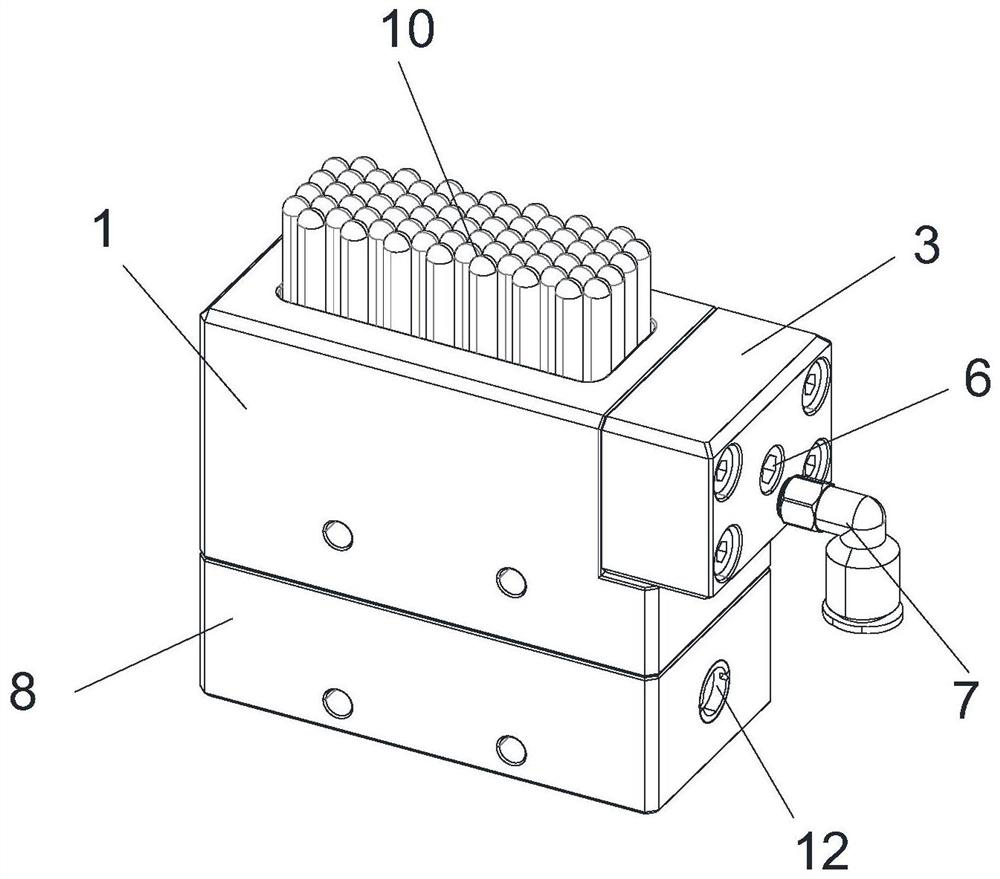
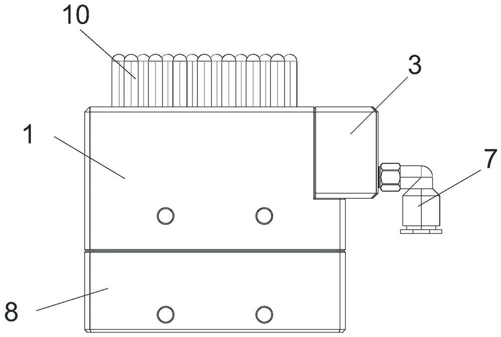
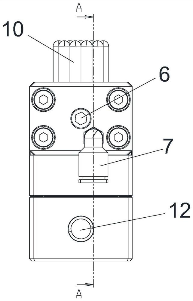
[0052] The embodiment of the present invention provides a flexible clamp that combines thread self-locking and pneumatic locking composite device, such as Figure 1-Figure 9 As shown, it includes: an upper box body 1, a first through hole is arranged on the right side of the upper box body 1, a sliding plate 2 is slidably arranged in the first through hole, and a fixed box 3 is arranged on the right side of the upper box body 1, A cavity is arranged in the fixing box 3, a piston plate 4 is slidably arranged in the cavity, a threaded hole and a first air hole 5 are arranged on the right side of the cavity, a jack screw 6 is arranged in the threaded hole, and the fixing box is 3. Set the quick-insertion nozzle 7 on the right side.
[0053] The working principle and beneficial effects of the above technical solutions are as follows: when in use, the top screw 6 is rotated, and the top screw 6 rotates in the threaded hole to drive the piston plate 4 to slide leftward in the cavity...
Embodiment 2
[0055] On the basis of the above Example 1, as Figure 1-Figure 6 As shown, the quick-insertion air nozzle 7 is in communication with the first air hole 5, and the first air hole 5 is in communication with the cavity;
[0056] The left side wall of the piston plate 4 is in contact with the right side wall of the sliding plate 2;
[0057] The fixed box 3 and the upper box 1 are fixedly connected by a plurality of first bolts.
[0058] The working principle and beneficial effects of the above technical solutions are as follows: the fixing box 3 is fixed on the right side wall of the upper box body 1 through the first bolt, the quick-insertion air nozzle 7 is communicated with the first air hole 5, and after the quick-insertion air nozzle 7 is connected to the air source, The gas can enter the first air hole 5 from the quick-insertion air nozzle 7, then enter the cavity, and squeeze the piston plate 4, and then the piston plate 4 squeezes the sliding plate 2, thereby achieving t...
Embodiment 3
[0060] On the basis of embodiment 1 or 2, as Figure 1-Figure 6 As shown, the lower end of the upper box 1 is provided with a lower box 8, the lower box 8 and the upper box 1 are fixedly connected by a plurality of second bolts, and the lower box 8 and the upper box 1 are fixedly connected. A partition 9 is arranged therebetween, a plurality of second through holes are arranged in an array on the partition 9, and a support column 10 is slidably arranged in the second through hole, and the support column 10 slides up and down along the second through hole.
[0061] The working principle and beneficial effects of the above technical solutions are as follows: a lower box 8 is fixedly installed at the lower end of the upper box 1 by means of second bolts, a partition 9 is arranged between the upper box 1 and the lower box 8, and the partition 9 opens A plurality of second through holes, a support column 10 is arranged in the second through hole, the support column 10 is slidably c...
PUM
 Abstract
Description
Claims
Application Information
 - R&D
- Intellectual Property
- Life Sciences
- Materials
- Tech Scout
- Unparalleled Data Quality
- Higher Quality Content
- 60% Fewer Hallucinations
Browse by: Latest US Patents, China's latest patents, Technical Efficacy Thesaurus, Application Domain, Technology Topic, Popular Technical Reports.
© 2025 PatSnap. All rights reserved.Legal|Privacy policy|Modern Slavery Act Transparency Statement|Sitemap|About US| Contact US: help@patsnap.com