Rotary roller elevator capable of achieving stable transmission

A rotary and elevator technology, applied in the direction of lifting frames, conveyor objects, lifting devices, etc., can solve the problems of large height difference, high cost, low manual handling efficiency, etc., and achieve the effect of facilitating automatic feeding and ensuring stability.

Pending Publication Date: 2021-12-24
江苏历漠智能装备有限公司
View PDF0 Cites 0 Cited by
  • Summary
  • Abstract
  • Description
  • Claims
  • Application Information

AI Technical Summary

Problems solved by technology

[0002] In the production process, it is often necessary to move the accumulated goods from high to low to facilitate transportation through the external transportation platf

Method used


Image

  • Rotary roller elevator capable of achieving stable transmission
  • Rotary roller elevator capable of achieving stable transmission
  • Rotary roller elevator capable of achieving stable transmission

Examples


Embodiment 1

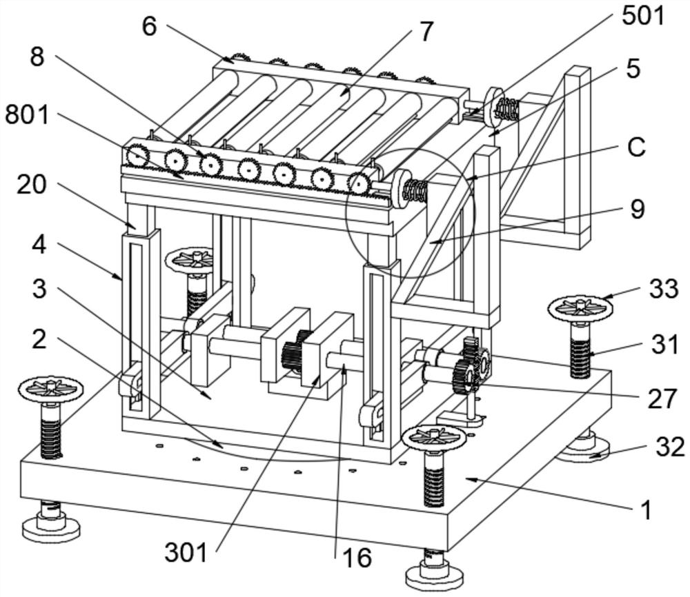
[0029] see Figure 1 to Figure 9 , the present invention provides a technical solution: a rotary drum lift capable of stable transmission, comprising a base 1, the upper surface of the base 1 is provided with a rotating table 2 that rotates at a fixed axis, and the upper surface of the rotating table 2 is fixedly connected with an installation platform 3, The four corners of the upper surface of the installation platform 3 are fixedly connected with the limit column 4, and the lift platform 5 is arranged directly above the limit column 4. The upper surface of the lift platform 5 is symmetrically provided with a guide rail 501, and the guide rail 501 is provided with a conveying platform 6. On the conveying platform 6 A feeding mechanism is provided, and the feeding mechanism includes several eccentric rollers 7 rotating on the inner wall of the conveying platform 6 with fixed axes. 8 intermeshed tooth plates-801, one side of the limit column 4 is fixedly installed with an incl...

Embodiment 2

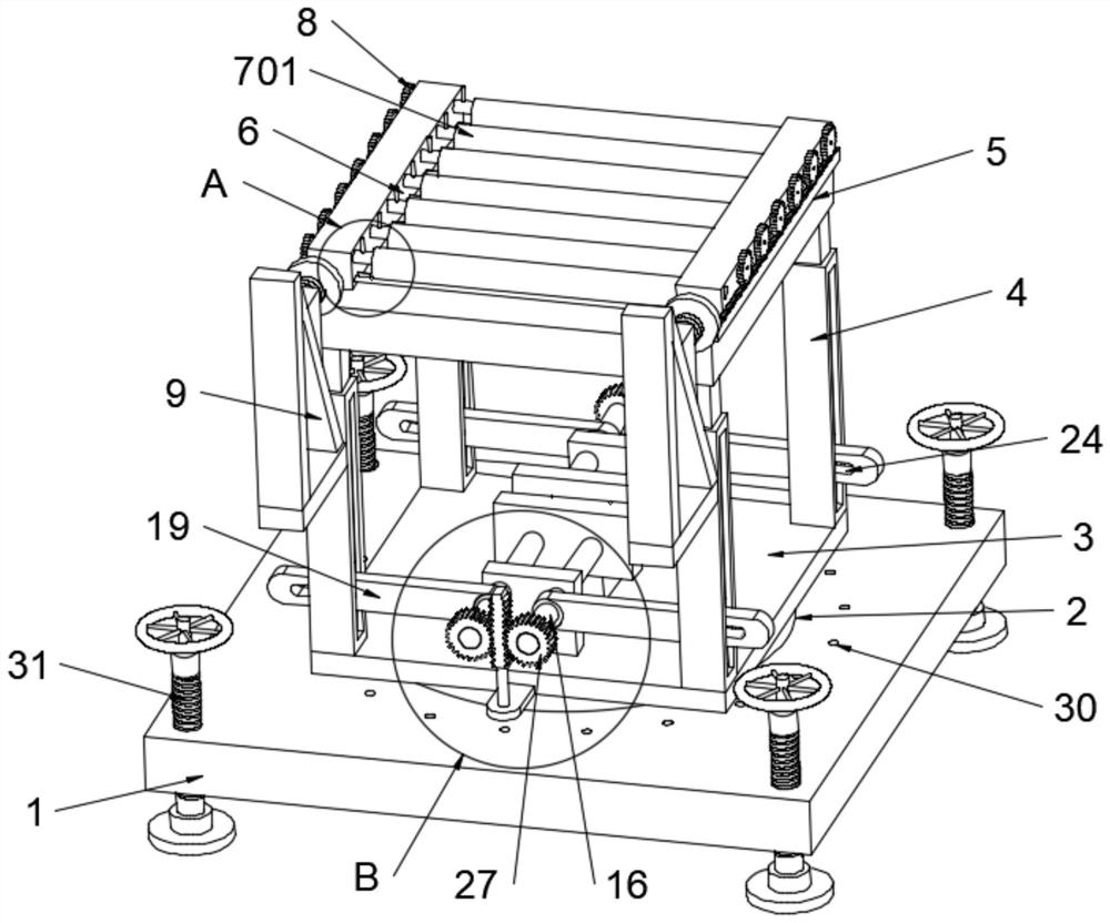
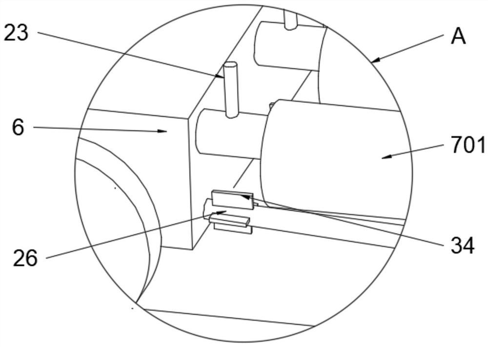
[0044] Such as Figure 1 to Figure 10 As shown, on the basis of the first embodiment, the difference is that the eccentric roller one 7 is replaced by the second eccentric roller 701, and the specific replacement method is that the material mechanism includes the second eccentric roller 701, and the second eccentric roller 701 is provided with several, several eccentric rollers The two 701 intervals are distributed on the inner wall of the conveying platform 6. The output shafts at both ends of the eccentric roller 7 run through the inner wall of the conveying platform 6 and are fixedly connected with the gear 1 8.

[0045] By setting the eccentric roller 2 701 with the eccentric lower axis distributed up and down on the inner wall of the conveying platform 6 at intervals, the shaking frequency of the goods on the conveying platform 6 can be increased, and the dust accumulated on the surface of the goods can be quickly shaken off by increasing the shaking frequency .

[0046]...


PUM


Abstract

The invention discloses a rotary roller elevator capable of achieving stable transmission, which comprises a base; a rotary table rotating around a fixed axis is arranged on the upper surface of the base; a mounting platform is fixedly connected to the upper surface of the rotary table; limiting columns are fixedly connected to the four corners of the upper surface of the mounting platform; a lifting platform is arranged directly above the limiting columns; guide rails are symmetrically arranged on the upper surface of the lifting platform; a conveying platform is arranged on the guide rails; a feeding mechanism is arranged on the conveying platform, and the feeding mechanism comprises a plurality of eccentric rollers I rotating around a fixed axis on the inner wall of the conveying platform, and output shafts of the eccentric rollers I penetrate through the outer wall of the conveying platform and are fixedly connected with gears I; toothed plates I meshed with the gears I are arranged at the bottoms of the gears I; an inclined plate is fixedly mounted on one side of each limiting column; and push rods for feeding of the eccentric rollers I are symmetrically arranged on the side, close to the inclined plate, of the conveying platform. The rotary roller elevator capable of achieving the stable transmission provided by the invention has the advantages of being convenient to feed, safe and stable, and the problems in the background technology are solved.

Description

technical field [0001] The invention relates to the technical field of lifting equipment, in particular to a rotary drum lift capable of stable transmission. Background technique [0002] In the production process, it is often necessary to transport the accumulated materials from high to low to facilitate transportation through the external transportation platform. Simply relying on manual transportation of the materials to the external transportation platform, due to the large height drop, Manual handling is inefficient and expensive. Therefore we need a rotary drum lift that can be stably transmitted. Contents of the invention [0003] The purpose of the present invention is to provide a rotary drum lift that can be transported stably, which has the advantages of convenient feeding, safety and stability, and solves the problems raised in the background technology. [0004] In order to achieve the above object, the present invention provides the following technical solu...

Claims


Application Information

Patent Timeline
IPC IPC(8): B65G13/12B65G13/071B65G45/10B08B1/02B08B7/02B66F7/06B66F7/28
CPCB65G13/12B65G13/071B65G45/10B08B7/02B08B1/02B66F7/0633B66F7/28
Inventor 刘平
Owner 江苏历漠智能装备有限公司
Why Eureka
Try Eureka