A midpoint clamp circuit, control device and control method

A clamping circuit and control equipment technology, which is applied to electrical components, output power conversion devices, and AC power input into DC power output, etc. Achieve the effect of improving the reliability of the circuit, improving the service life, and avoiding overvoltage damage.

Active Publication Date: 2022-03-15
广东省洛仑兹技术股份有限公司
View PDF5 Cites 0 Cited by
  • Summary
  • Abstract
  • Description
  • Claims
  • Application Information

AI Technical Summary

Problems solved by technology

However, this method will cause the inductor current in the NPC circuit to continue to flow only through the antiparallel diodes of each switch tube, which will further cause a sudden change in the level of the neutral node on the side of the inductor in the NPC circuit, causing some switch tubes to withstand Damaged by high voltage stress, reducing the reliability of the power supply

Method used


Image

  • A midpoint clamp circuit, control device and control method
  • A midpoint clamp circuit, control device and control method
  • A midpoint clamp circuit, control device and control method

Examples


Embodiment approach

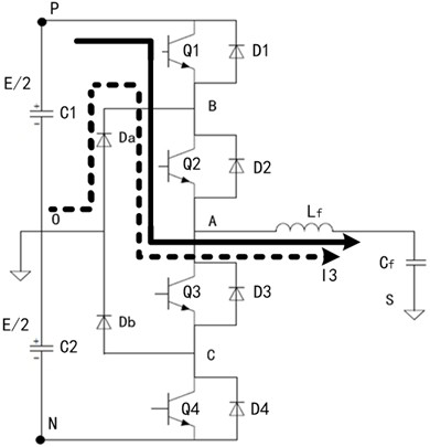
[0057] In the first embodiment, corresponding to the above image 3 For the problems involved in the midpoint clamping circuit shown, if the controller 502 acquires that the current switching cycle is a positive half cycle, control the first switching tube Q1, the third switching tube Q3 and the fourth switching tube Q4 to be disconnected, and control The second switch tube Q2 is turned on. Further, on the premise of controlling the first switching tube Q1, the third switching tube Q3 and the fourth switching tube Q4 to be turned off, the second switching tube Q2 can be controlled to maintain a conduction state within a preset period of time, after the preset period of time , switch the second switching tube Q2 from the on state to the off state. Wherein, the specific value of the preset time period can be customized by the user according to historical experience or actual needs.

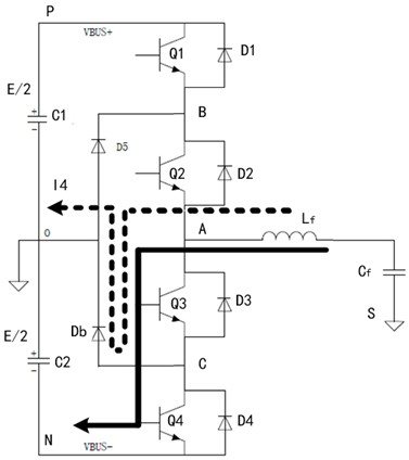
[0058] see Figure 6 , Figure 6 It is one of the schematic diagrams of the current directio...


PUM


Abstract

The present application provides a midpoint clamping circuit, a control device and a control method. The midpoint clamping circuit includes a main circuit, a controller and a detector. The main circuit includes a switch tube circuit, a diode clamp circuit and an inductor. Wherein, the switching tube circuit includes a first switching tube, a second switching tube, a third switching tube and a fourth switching tube connected in series in sequence. The detector is used for monitoring the state of the power supply, and the controller is respectively connected with the detector and the control terminals of each switching tube. According to the detection information sent by the detector, the controller in the neutral point clamping circuit provided by this application controls the on-off of each switch tube and makes the second switch tube or the third The switch tube provides a freewheeling circuit for the inductor current, reduces the voltage difference across the second switch tube or the third switch tube, effectively prevents the switch tube from being damaged due to excessive voltage stress, and improves the service life of the device and the reliability of the circuit.

Description

technical field [0001] The present application relates to the field of circuit control, in particular to a midpoint clamping circuit, a control device and a control method. Background technique [0002] Neutral Point Clamped (NPC for short) circuits are widely used in rectifier circuits and inverter circuits. When the power supply connected to the NPC circuit is abnormal or needs to be shut down, it is necessary to turn off the driving pulse of the switching tube in the NPC circuit. A common practice at present is to directly turn off the driving pulses of all switching tubes in the NPC circuit, so as to achieve the purpose of turning off the switching tubes and stopping the power output. However, this method will cause the inductor current in the NPC circuit to continue to flow only through the antiparallel diodes of each switch tube, which will further cause a sudden change in the level of the neutral node on the side of the inductor in the NPC circuit, causing some switc...

Claims


Application Information

Patent Timeline
Patent Type & Authority Patents(China)
IPC IPC(8): H02M1/34H02M7/797H02M7/217H02M7/487
CPCH02M1/34H02M7/797H02M7/217H02M7/487
Inventor 周瑜谭果
Owner 广东省洛仑兹技术股份有限公司
Why Eureka
Try Eureka