Cabinet adjusting leg

A technology for adjusting feet and cabinets, applied in the field of cabinet adjusting feet, can solve the problems of difficult installation, easy deflection of the assembly position of the adjusting feet, etc., and achieves the effect of reducing the difficulty of installation, avoiding the collapse of the cabinet body, and avoiding position deflection.

Pending Publication Date: 2021-12-28
博洛尼智能科技(青岛)有限公司
View PDF0 Cites 0 Cited by
  • Summary
  • Abstract
  • Description
  • Claims
  • Application Information

AI Technical Summary

Problems solved by technology

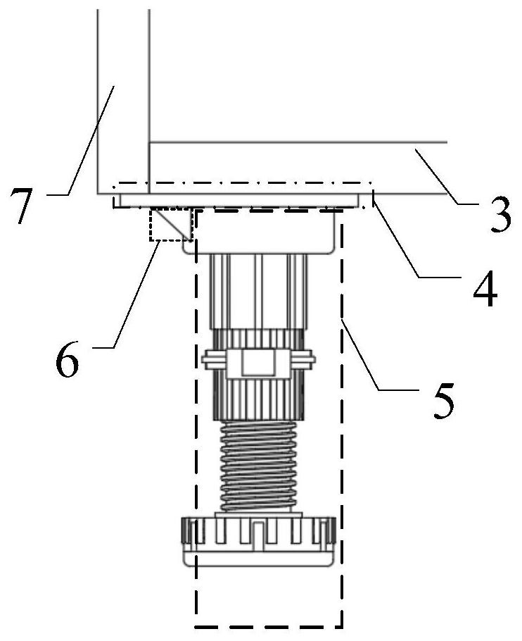
figure 2 It is another structural schematic diagram of adjusting feet in the prior art, such as figure 2 As shown, the adjustment foot includes a support plate 4 and a support column 5, by lengthening the support plate 4 to the side plate 7 of the cabinet, and setting a support rib 6 between the support plate 4 and the support column 5, thereby reducing the weight of the cabinet Place it on the bottom plate 3 and the side plate 7 to share the load bearing of the cabinet bottom plate 3 and avoid the risk of cabinet collapse. However, when this structure is assembled in the cabinet, since there is no positioning between the adjustment feet and the bottom plate 3 of the cabinet, the adjustment feet The assembly position is prone to deflection, and the installation is difficult

Method used


Image

  • Cabinet adjusting leg
  • Cabinet adjusting leg
  • Cabinet adjusting leg

Examples


Embodiment Construction

[0039] Certain terms are used, for example, in the description and claims to refer to particular components. Those skilled in the art should understand that hardware manufacturers may use different terms to refer to the same component. The specification and claims do not use the difference in name as a way to distinguish components, but use the difference in function of components as a criterion for distinguishing. As mentioned throughout the specification and claims, "comprising" is an open term, so it should be interpreted as "including but not limited to". "Approximately" means that within an acceptable error range, those skilled in the art can solve the technical problem within a certain error range and basically achieve the technical effect. The subsequent description of the specification is a preferred implementation mode for implementing the application, but the description is for the purpose of illustrating the general principle of the application, and is not intended...


PUM


Abstract

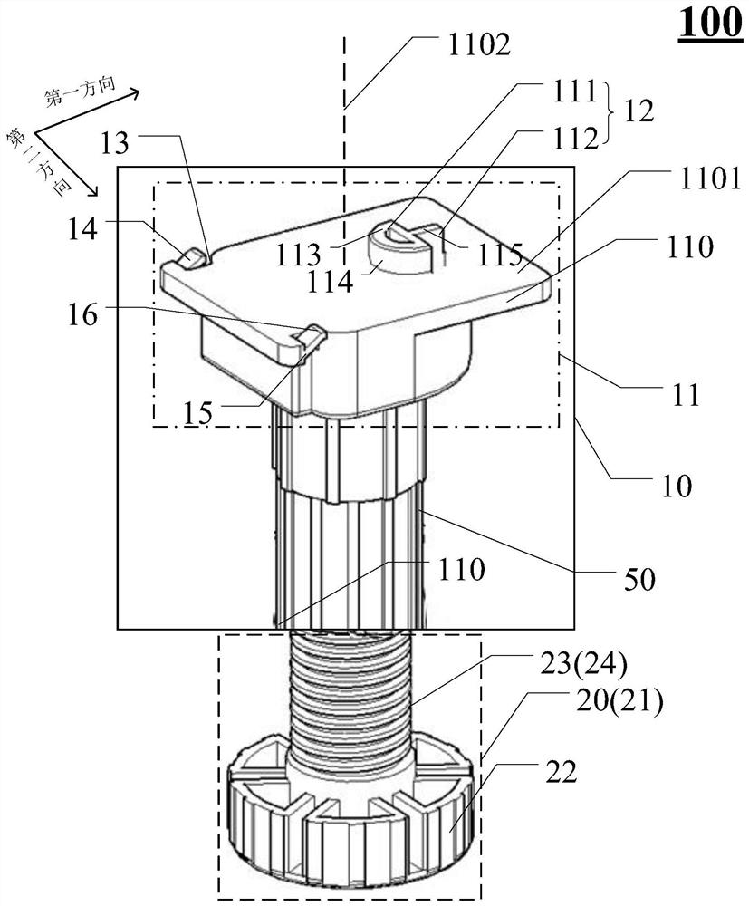
The invention discloses a cabinet adjusting leg, and belongs to the field of furniture. The cabinet adjusting leg comprises an upper part and a lower part; the upper part comprises a base, and the base is fixed with a cabinet body bottom plate; the base comprises a fixing plate and a fixing part, the fixing plate comprises a first center shaft, and the fixing part and the first center shaft are not overlapped; the fixing plate comprises at least one opening part, the fixing plate comprises a first edge and a second edge, the opening part is located on the side, facing the first edge, of the first center shaft, and the fixing part is located on the side, facing the second edge, of the first center shaft; the base further comprises at least one positioning clamp, the first end of the positioning clamp is fixedly connected with the fixing plate, and the second end of the positioning clamp protrudes in the direction away from the first face; the upper part comprises a supporting rod, and the supporting rod comprises a threaded hole and an internal thread located in the threaded hole; and the lower part comprises a screw which is in threaded connection with the supporting rod. Dual positioning between the cabinet body bottom plate and the adjusting leg base is achieved through the fixing part and the positioning clamp, position deflection between the adjusting leg base and the cabinet body bottom plate is avoided, and the installation difficulty is reduced.

Description

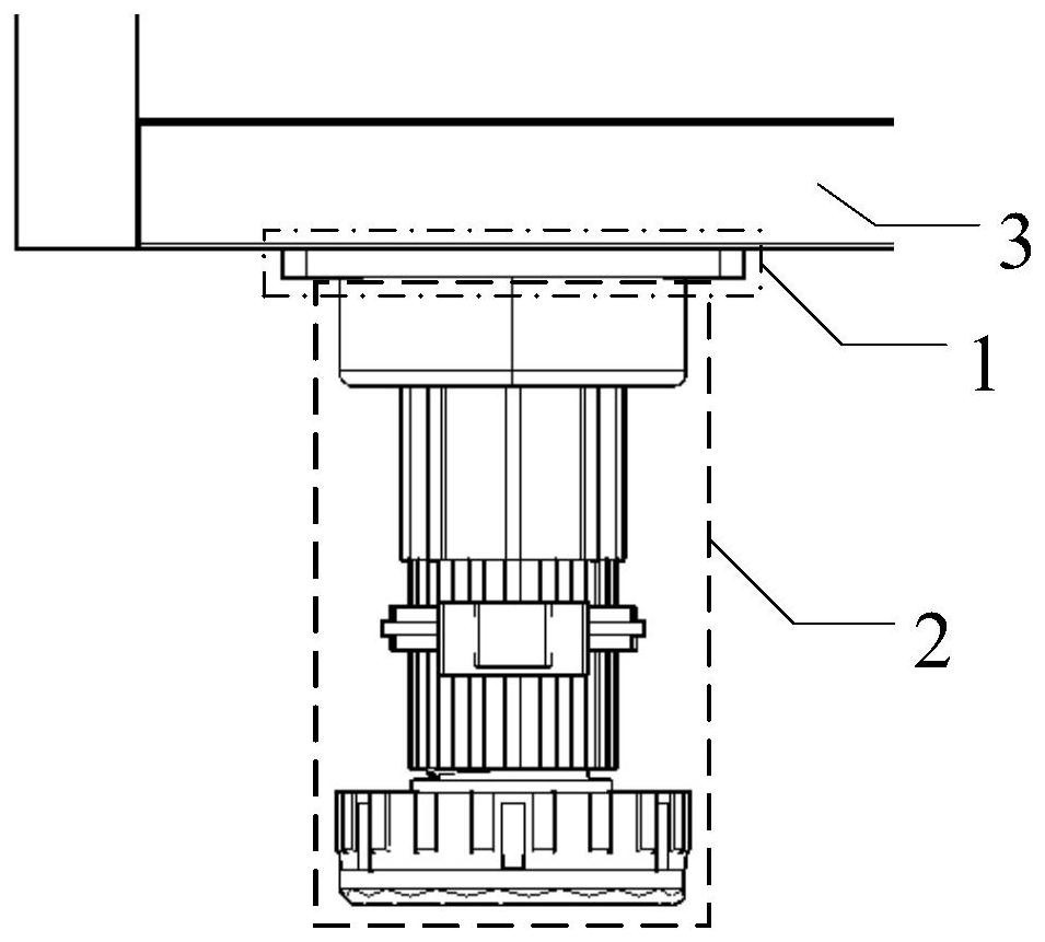
technical field [0001] The present application relates to the technical field of furniture, in particular to a cabinet adjusting foot. Background technique [0002] Most of the supporting feet of cabinets in daily life are non-adjustable, that is, the height is fixed, but users usually have different requirements for the height of furniture due to site restrictions and other reasons, so manufacturers need to adapt supporting feet of different heights, resulting in The increase in production costs is not conducive to market competition. [0003] Of course, there are also height-adjustable adjustment feet now. The existing adjustment feet mainly include: figure 1 with figure 2 Two are shown. figure 1 It is a structural schematic diagram of adjusting feet in the prior art, such as figure 1 As shown, the adjustment foot includes a support plate 1 and a support column 2, and the adjustment of the cabinet body is realized by fixing the support plate 1 to the bottom plate 3 of...

Claims


Application Information

Patent Timeline
Patent Type & Authority Applications(China)
IPC IPC(8): A47B91/02
CPCA47B91/024
Inventor 蔡明蔡兴国王庆彦王奇王庆有
Owner 博洛尼智能科技(青岛)有限公司
Why Eureka
Try Eureka