Eureka AIR delivers breakthrough ideas for toughest innovation challenges, trusted by R&D personnel around the world.

Automatic welding mechanism for stamping parts

A technology for automatic welding and stamping parts, applied in the field of stamping parts welding, can solve the problems that affect the service life of workpieces, rivets are prone to bending, and the surface shape of workpieces is damaged.

Active Publication Date: 2021-11-09
启东市海生冲压件有限公司
View PDF11 Cites 0 Cited by
  • Summary
  • Abstract
  • Description
  • Claims
  • Application Information

AI Technical Summary

Problems solved by technology

[0006] However, this scheme adopts the method of direct pressure riveting during riveting, which causes the rivet to be easily bent during the riveting process, which in turn affects the service life of the later workpiece, and this method of direct pressure riveting is easy to cause damage to the shape of the surface of the workpiece , cannot be carried out by automatic punching in the process of riveting

Method used


Image

  • Automatic welding mechanism for stamping parts
  • Automatic welding mechanism for stamping parts
  • Automatic welding mechanism for stamping parts

Examples


Embodiment 1

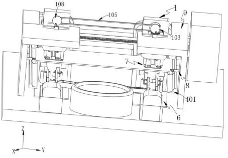
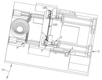
[0084] like Figure 1-3 As shown, an automatic welding mechanism for stamping parts, including:

[0085] drive unit 1;

[0086] A switching unit 2, the switching unit 2 is arranged under the driving unit 1, and is used for drilling and punching the riveting part;

[0087] A preload unit 3, which is arranged on one side of the drive unit 1, and is used to preload and guide the small metal plate;

[0088] A bending unit 4, the bending unit 4 is arranged on one side of the pretensioning unit 3 along the -X direction, and is used to bend the large metal plate;

[0089] Pushing unit 5, described pushing unit 5 is arranged on the side of described bending unit 4;

[0090] A nailing unit 6, the nailing unit 6 is arranged below the switching unit 2;

[0091] A welding unit 7, the welding unit 7 is arranged on one side of the pretensioning unit 3 along the +X direction;

[0092] When working, two metal plates of different sizes are pushed by the pushing unit 5. The large metal pla...

Embodiment 2

[0142] like figure 1 , Image 6 , Figure 10 As shown, the components that are the same as or corresponding to those in the first embodiment are marked with the corresponding reference numerals in the first embodiment. For the sake of simplicity, only the differences from the first embodiment will be described below. The difference between this embodiment two and embodiment one is:

[0143] The two sides inside the support 9 are provided with guide units 8, the guide unit 8 includes a guide plate 801 connected to one side of the support 9, a guide roller 802 connected to one side of the guide plate 801, and the guide roller 802 guides and fixes the large metal plate. It can prevent the position deflection of the large metal plate during processing, and further improve the processing accuracy.

Embodiment 3

[0145] like Figure 1-3 As shown, the components that are the same as or corresponding to those in the first embodiment are marked with the corresponding reference numerals in the first embodiment. For the sake of simplicity, only the differences from the first embodiment will be described below. This embodiment three and embodiment one, the difference of embodiment two is:

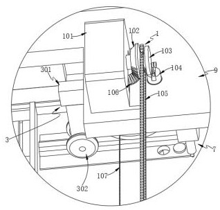
[0146] The first transmission chain 105 is set on the first helical gear 102 side, so that the crank transmission mechanism 103 can drive the second crank transmission mechanism 108 to rotate during the rotation process, and the sprocket 207 is set on the second helical gear 106 side, so that the second helical gear 106 side is set. The second helical gear 106 can drive the second transmission chain 107 to rotate during the rotation process, so that a plurality of small metal plates and large metal plates can be riveted and welded at one time, and the degree of automation is high.


PUM


Abstract

The invention provides an automatic welding mechanism for stamping parts. The automatic welding mechanism for stamping parts is characterized by comprising a driving unit, a switching unit, a pre-tightening unit, a bending unit, a pushing unit, a nail feeding unit and a welding unit, wherein the switching unit is arranged under the driving unit; the pre-tightening unit is arranged at one side of the driving unit; the bending unit is arranged at one side of the pre-tightening unit in the -X direction; the pushing unit is arranged at one side of the bending unit; the nail feeding unit is arranged under the switching unit; and the welding unit is arranged at one side of the pre-tightening unit in the +X direction. A large metal plate is guided in through the guide block, so that the parts, to be bent, of the two ends of the metal plate are fed into a bending punching groove, then the bending block moves downwards under the control of an internal driving element, the two sides of the large metal plate are bent, and in the subsequent riveting and welding process, the positioning and guiding can be performed by using the bending position and the bending punching groove.

Description

technical field [0001] The invention relates to the technical field of stamping parts welding, in particular to an automatic welding mechanism for stamping parts. Background technique [0002] Stamping welding is a common production process in hardware processing. Common road metal plate signs usually require atmospheric pressure welding technology in production. Generally, stamping welding is used to first stamp and bend, and then weld reinforcing ribs on the surface of the metal plate. Plates to prevent the metal plate signs from being hung up by strong winds on the road. [0003] Chinese patent CN 104889691 A discloses a stamping and welding production line, the stamping and welding production line includes a feeding mechanism, a cutting and repositioning mechanism, a stamping detection mechanism, a clamping detection mechanism, a welding mechanism, a welding detection mechanism, a main electric control cabinet and an area The sensors are all installed on the factory flo...

Claims


Application Information

Patent Timeline
Patent Type & Authority Applications(China)
IPC IPC(8): B23P23/06
CPCB23P23/06
Inventor 陆善忠
Owner 启东市海生冲压件有限公司
Why Eureka
Eureka Blog
Learn More