A push rod pressing device, positioning assembly and positioning device
A technology of pressing device and push rod, which is applied in the direction of transportation and packaging, space navigation equipment, space navigation equipment, etc., and can solve difficult and expensive problems
- Summary
- Abstract
- Description
- Claims
- Application Information
AI Technical Summary
Problems solved by technology
Method used
Image
Examples
Embodiment 1
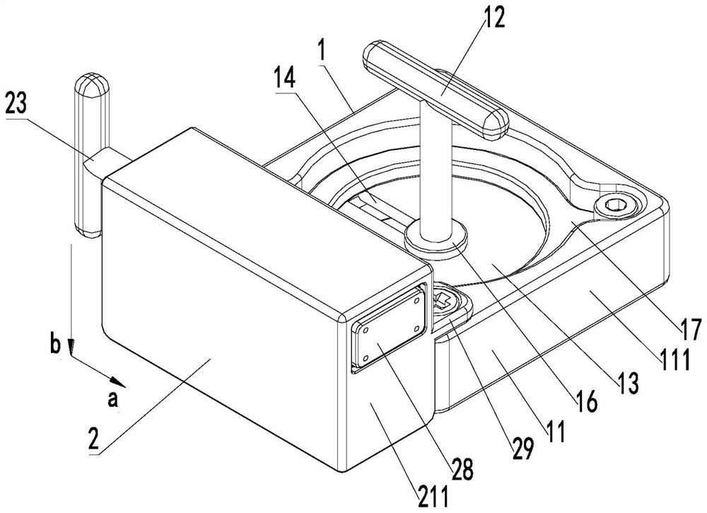
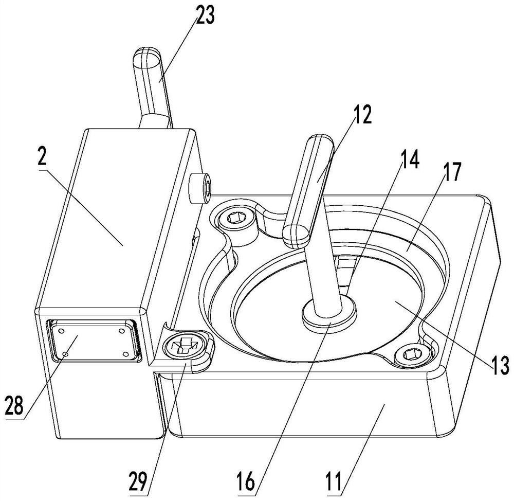
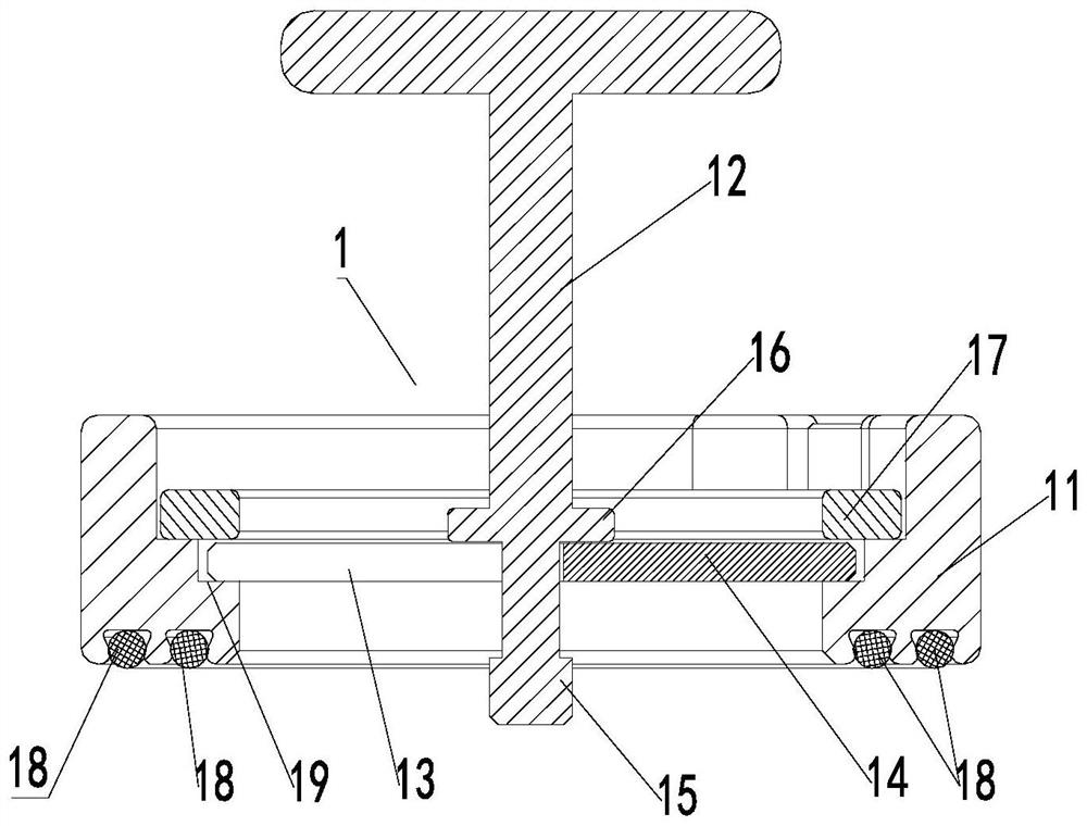
[0044] Such as Figure 1 ~ Figure 3 As shown, a push rod pressing device of this embodiment includes a worktable movable restraint seat 1 and a restraint head 2, and the restraint head 2 is installed on the workbench movable restraint seat 1, and the restraint head 2 The constraint direction is arranged at an angle to the installation direction of the movable constraint seat 1 of the workbench, figure 1 The direction of the middle arrow a is the constraint direction of the constraint head 2, and the direction of the arrow b is the installation direction of the movable constraint seat 1 of the workbench; the movable constraint seat 1 of the workbench includes the main support of the constraint seat, the tightening handle 12 and the movable block 13 The main support of the constraint seat is provided with an assembly through hole, and the movable stopper 13 can be embedded in the assembly through hole of the main support of the constraint seat so that it can rotate along the cir...
Embodiment 2
[0052] On the basis of Example 1, such as Figure 4 As shown, the constraining head 2 of this embodiment includes a constraining head main support, a rotating push handle 23, an elastic member, and a sliding constraining head 25. A pre-compression channel is formed in the constraining head main support, and the pre-compression channel The two ends are the operation end and the pre-compression end respectively, and the said rotary propulsion handle 23 is threadedly connected in the operation end of the said pre-compression channel and elastically connected with the sliding constraint head 25 through an elastic member; A circle of annular steps is provided on the inner sidewall (the said annular step can be a square annular step, also can be a circular annular step, or be other polygonal annular steps), and the outer sidewall of the sliding constraint head 25 is provided with an annular platform Shoulder 251, the annular shoulder 251 abuts on the annular step, and the free end o...
Embodiment 3
[0058] Such as Figure 5 and Figure 6 As shown, a positioning assembly of this embodiment includes the push rod pressing device described in Embodiment 1 or Embodiment 2, and also includes an angle gauge 3, and the bottom of the angle gauge 3 is provided with a guide pin post 31, so that A rubber strip 32 is provided on the inner side of the angle gauge 3 . The rubber strip on the angle gauge can protect the load equipment while ensuring a certain friction. Positioning on the table is possible by setting on the guide pin post on the angle gauge.
[0059] Such as Figure 5 and Figure 6As shown, a preferred solution of this embodiment is that the inner surface of the angle gauge 3 is provided with a plurality of through grooves with the top through and the bottom closed, and rubber strips 32 are embedded in the grooves. The top of 3 is fixed with the briquetting block 33 that compresses described rubber bar 32. A pressing block can be used to compress and fix the rubber ...
PUM
 Abstract
Description
Claims
Application Information
 - R&D
- Intellectual Property
- Life Sciences
- Materials
- Tech Scout
- Unparalleled Data Quality
- Higher Quality Content
- 60% Fewer Hallucinations
Browse by: Latest US Patents, China's latest patents, Technical Efficacy Thesaurus, Application Domain, Technology Topic, Popular Technical Reports.
© 2025 PatSnap. All rights reserved.Legal|Privacy policy|Modern Slavery Act Transparency Statement|Sitemap|About US| Contact US: help@patsnap.com


